
Ducati Diavel Service Manual: Removing the front footrest brackets
Note
The assembly of the front footrests is described only for the right one (2) but it is the same also for the left one.
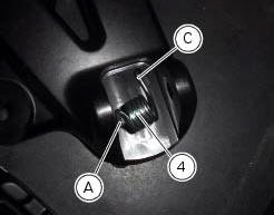
Place the spring (4) bringing the end (a) onto the footrest (2).
Place the footrest (2) in the correct position, by inserting the end (c) of the spring (4) in the hole (d) of the frame plate.
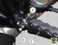
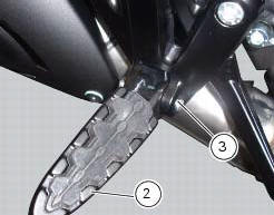
Apply the recommended grease to the pin (3).
Insert pin (3) orienting it as illustrated.
Lock the pin by inserting the circlip (5).
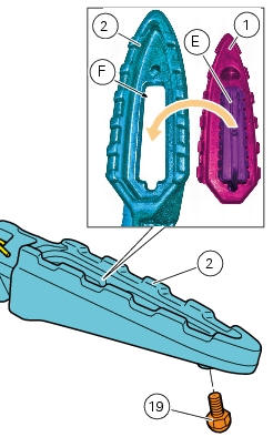
If previously removed, refit the rubber footrest (1) on the footrest (2), inserting pad (e) into the seat (f) in the footrest (2) until it becomes engaged.
Note
To better insert the rubber footrest (1) use lubricant specific for rubber.
Start the screw (19) on the bottom side of the footrest (2) and tighten to the specified torque.
 Refitting the front footrests
Note
The assembly of the front footrests is described only for the right one
(2) but it is the same also for the left one.
Place the spring (4) bringing the end (a) onto the footrest (2).
Place ...
 Reassembling the front footrest brackets
To remove the front rh footrest bracket (6) it is necessary to remove the
rear brake master cylinder reservoir (by leaving
it connected to the braking system), and the rear brake lever from the bra ...
Other materials:
Suspensions
Front
Hydraulic upside-down fork provided with external adjusters
for rebound and compression damping and preload (for inner
springs of fork legs).
Stanchion diameter:
50 mm, coated.
Rear wheel travel:
120 mm
Rear
The shock absorber is adjustable for rebound and
compression, with remot ...
Replacing the high and low beam bulbs
Before replacing a burnt-out bulb, make sure that the new
bulb complies with the voltage and wattage specified in the
"wiring diagram", page 179. Always test the new bulb
before refitting any parts you have removed.
Fig. 150 Shows the locations of the low beam bulbs (lo), high
beam ...
Checking the fuses
The main fuse box (1) and the secondary one (2) are located in the tool tray;
to reach the fuse box remove the seat as
specified under sect. 5 - 3 "Removal of the seat".
The fuses are accessed by removing the cover, which shows the ampere ratings and
mounting locations.
For ampere ratings ...