
Ducati Diavel Service Manual: Reassembling the frame and the lateral footrests
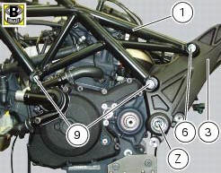
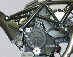
Apply the recommended grease to the thread of the pins (9) and of the nuts (8).
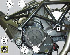
Place the frame (1) and the brackets (2) and (3) on the engine block. Start the pins (9) by holding the nuts (8) and insert without tightening the screws (6) into the adjusters (4).
Position and fix the rear shock absorber support to the engine crankcases and the swingarm brackets (sect. 7 - 12, Refitting the shock absorber support).
Tighten the screw (v) on the swingarm shaft right side to a torque of 72 nm +/- 5% (sect. 3 - 3, Frame torque settings), by holding the screw (z) on the left side.
Tighten the indicated front nut (8) to a torque of 60 nm +/- 5% (sect. 3 - 3, Frame torque settings), by holding the pin (9) on the left side.
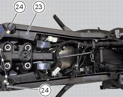
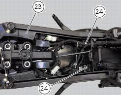
Reassemble the tool tray (23), as described in the following paragraph, by tightening the rear screws (24) to 14 nm +/- 5% (sect. 3 - 3, Frame torque settings).
Tighten the indicated rear nut (8) to a torque of 60 nm +/- 5% (sect. 3 - 3, Frame torque settings), by holding the pin (9) on the left side.
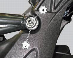
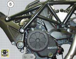
Work first on the left side and then on the right one, remove the special screws (6) and tighten to a torque of 0.5 Nm +/- 10% (sect. 3 - 3, Frame torque settings) the adjusters (4) and make sure they are fully home on the rear plates of the rear subframe.
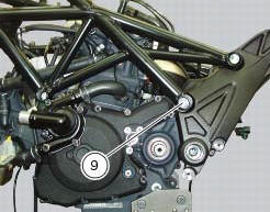
Locate service tool no. 88713.3166 On the ring nut (5) and fit the torque wrench to the tool.
Hold the clearance adjusters (4) and tighten the ring nuts (5) to a torque of 100 nm +/-5% (sect. 3 - 3, Frame torque settings).
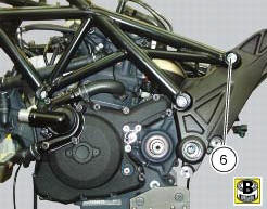
Lubricate thread and underside of special screws (6), then start them on the frame, and tighten them to a torque of 55 nm +/-5% (sect. 3 - 3, Frame torque settings).

Tighten the front screws (24) to a torque of 14 nm +/- 5% (sect. 3 - 3, Frame torque settings) that retain the tool tray (23).
 Reassembly of structural components and the frame
Check for the nuts with clips (8).
Apply recommended grease on the threads of the adjusters (4) and the ring
nuts (5) having care not to have grease on
the surface (c) of the adjusters.
Tig ...
 Reassembly of the tool tray
Place the tool tray unit (23) on the lateral brackets (2) and (3) by
tightening the screws (24) to 14 nm +/- 5% (sect. 3-3,
Frame torque settings).
If the handle guide (32) has been previously r ...
Other materials:
Refitting the swingarm
Apply the recommended threadlocker to the screws (7).
Install the lower chain guard (15) on the swingarm (8), fastening it with the
screws (7): tighten the screws (7) to a torque
of 4 nm +/- 10% (sect. 3 - 3, Frame torque settings).
Locate the swingarm (8) on the frame.
Lubricate with ...
Dtc (ducati traction control) setting function
This function allows you to customise the level of dtc intervention (ducati
traction control) or disable it for every riding
mode.
To access the function it is necessary to view the ""setting" menu", using
buttons (1) "s" or (2) "t" select the "riding
mode" function and press the reset butt ...
Riding mode set indication
This function indicates the "riding style" set for the vehicle.
Three "riding modes" are available: sport, touring and
urban.
Each riding mode can be changed using the "riding
mode" function.
Note
The background of the riding mode (sport, touring
or urban) i ...