
Ducati Diavel Service Manual: Refitting the gear selector lever
Position the gearbox drum selector fork in the centre of the gear rollers.
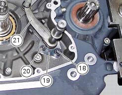
Position the gear selector lever (21) together with control shaft, spring and plate into the chain-side crankcase half.
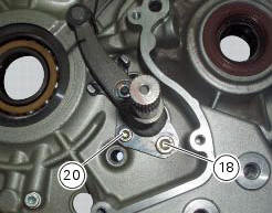
Insert the screws (18) and (20) with the spacer (19).
Temporarily fit gear change lever (or a service lever) and engine pinion and shift to neutral gear.
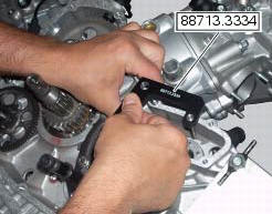
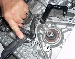
Place the tool 88713.3334 On the gear claw.
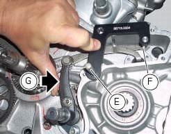
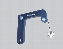
Place the tool 88713.3334 Inserting the clutch rod (e) into the tool hole, block the pin (f) of the tool in the gear claw pressing with the hand in the point (g) (claw stroke lock plate) towards the right, as shown in photo.
Tighten the screw (18) in this position to a torque of 36 nm (min. 34 Nm - max. 38 Nm) and screw (20) to a torque of 16 nm (min. 15 Nm - max. 17 Nm) (sect. 3 - 3, Engine torque settings).
Warning
Make sure that the gear selector lever fixing screws (18) and (20) are those indicated in our spare parts catalogue. They Must be screws of class 12.9 In order to respect the tightening torque indicated above (sect. 3 - 3, Engine torque settings).
Start tightening the first screw (18), and continue with screw (20).

Remove service tool no.
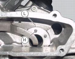
Check that the pin (h) placed on the gear drum is axially to the notch (l) on the gear claw (with gear in neutral).
With the gearbox in neutral, check that the lever travel is the same when shifting up and down. The same should apply when a gear is engaged.
Operate the gearchange lever and turn the front sprocket at the same time to check that all the gears engage when shifting up and down.
Remove the previously installed lever and sprocket.
 Refitting the gear interlock plunger and pawl assembly
On the special screw (3), fit the gear pawl lever (4), orienting it as shown
in the figure, the washer (2) with the square
edge side (d) facing the clutch-side crankcase half, and the spring (1),
...
 Gearbox shafts
Shim, thickness 1
Gearbox primary shaft
Shim, thickness 0.5
Needle roller bearing
5Th speed driving gear
Splined washer, thickness 0.5
Circlip
3Rd- 4th speed driving gear
6Th sp ...
Other materials:
Clutch
Screw
Ring
Clutch spring
Pressure plate
Bearing
Circlips
Nut
Belleville washer
Clutch plates
Belleville washer
Flat ring
Clutch centre
Spacer
Clutch lifter
Spare parts catalogue
Diavel abs clutch
Diavel carbon
abs
clutch
Important
Bold reference numbers in t ...
Engine torque settings
*Dynamic safety-critical point; tightening torque must be within nm +/-5%.
Note
For product specifications and symbols, refer to paragraph "product
specifications" (sect. 1 - 2). ...
Topping up the electrolyte
Warning
Before carrying out any operations on the battery, keep in mind the
safety standards (sect.1 - 3, General safety rules).
The electrolyte in the battery is toxic and can cause burns if it comes into
contact with the skin because it contains
sulphuric acid. Wear protective clothing, a ...