
Ducati Diavel Service Manual: Reassembly of the control unit
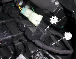
Insert the control unit (4) into the protecting sheath (5) and position it on the airbox.

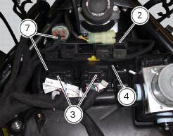
Position the relay supporting bracket (2) by starting and tightening the screws (1) to a torque of 6 nm +/- 10% (sect. 3 - 3, Frame torque settings), and connect the control unit connectors (3).

 Removal of the control unit
Loosen the screws (1) and remove the relay supporting bracket (2), disconnect
the connectors (3) and remove the control
unit (4) from the vehicle.
...
 Fuel system circuit
The fuel system circuit consists of:
An electric pump, driven by the injection relay, which is in turn
controlled by the ecu (engine control unit)
A fuel filter
A pressure regulator
Two i ...
Other materials:
Refitting the front brake system
While refitting the system, pay special attention to the orientation of the
pipe couplings (24) on the pump and the pipes
(13) and (20) on the callipers (9) and (18).
Warning
If incorrectly positioned, the hose can affect brake operation and
foul moving parts. Position the hose as shown in th ...
Operating principle and characteristics of the ride-by-wire system
The engine control system of the diavel uses a ride-by-wire system with
motorised throttle valves. This eliminates all
direct connection with metal cables between the throttle grip and the throttle
valves themselves. Cables are used to
rotate the aps potentiometer, which generates an electric ...
Oil cooler
Oil cooler
Vibration damper mount
Spacer
Screw
Nipple
Aluminium gasket
Oil delivery hose
Screw
Plate
Bracket
Screw
Engine oil pressure sensor
Sealing washer
Heat guard
Exhaust protection
Screw
Washer
Spacer
Spare parts catalogue
Diavel abs oil cooler
Dia ...