
Ducati Diavel Service Manual: Disassembly of gear interlock plunger and pawl assembly
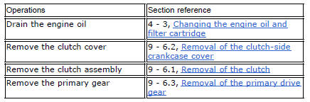
Unscrew the interlock plunger screw (5) and remove the seal (6), spring (7) and the detent ball (8).
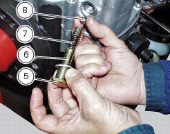
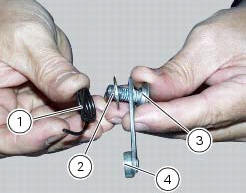
Unscrew the clutch-side crankcase half screw (3) and remove the pawl (4), washer (2) and spring (1).
 Removal of the gear selector lever
Unscrew and remove the fixing screws (18) and (20) of the complete gear
selector lever (21) and collect the spacer (19).
Remove the gearchange mechanism complete with the shaft, spring, and s ...
 Refitting the gear interlock plunger and pawl assembly
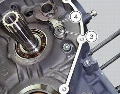
On the special screw (3), fit the gear pawl lever (4), orienting it as shown
in the figure, the washer (2) with the square
edge side (d) facing the clutch-side crankcase half, and the spring (1),
...
Other materials:
Electrical power for lighting and signalling devices
The front and rear running lights consist of led units with light conduits.
As a result, the light source is not visible as the
light is diffused through the surface of the light conduit.
These two images illustrate the front and rear running lights with light
conduits.
The figure ...
Limited liability
The liability of ducati under this emission control systems
warranty is limited solely to the remedying of defects in
material or workmanship by an authorized ducati motorcycle
dealer at its place of business during customary business
hours. This warranty does not cover inconvenience or l ...
Menu 2 on/off function
This function turns off and back on the menu 2.
If menu 2 is disabled, the functions for average fuel
consumption (cons.Avg), instantaneous fuel consumption
(cons.), Average speed (speed avg), trip time (trip time)
and air temperature (air) will no longer be displayed in the
"main screen ...