
Ducati Diavel Service Manual: Refitting the gearchange mechanism
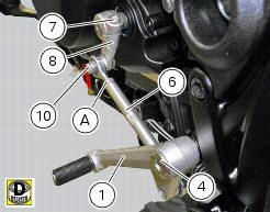
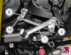
Make sure that the gearchange linkage assembly (6) is installed with the ball joint with a left-hand thread (a) facing the lever (8).
Apply the recommended grease to the non-threaded surface of the pin (4).
Fit the first o-ring (5) in the pin (4).
Start the pin (4) in the gearchange lever (1). Smear recommended grease on the second o-ring (5). Insert the second o Ring (5) and the washer (9).
Apply the recommended threadlocker to the threaded side of the pin (4). Fit the gearchange lever (1) on the footrest bracket and tighten the pin (4) to a torque of 23 nm +/- 10% (sect. 3 - 3, Frame torque settings).
Fit the lever (8) on the gearchange control assembly, and start the screw (10).
Tighten the screw (10) to the torque of 10 nm +/- 10% (sect. 3 - 3, Frame torque settings).
Fit the gear control unit inserting the lever (8) on the gear control pin, apply threadlocker on the screw (7) and insert it on the lever (8).
Tighten the screw (7) to a torque of 10 nm +/- 10% (sect. 3 - 3, Frame torque settings).
 Disassembly of the gearchange mechanism
Refer to the exploded view at the beginning of this section for indications
on disassembly and renewal of gearchange
components.
If the bushing (2) inside the pedal (1) needs replacing, grease t ...
 Fork
Fork
...
Other materials:
Dashboard diagnosis
This function identifies any abnormal vehicle behaviours.
The dashboard activates any abnormal vehicle behaviours in real time (errors).
At key-on (at the end of the check) one or more "errors" are displayed in red
(only if they are active).
When an "error" is triggered, the indication (r ...
Suspensions
Front
Hydraulic upside-down fork provided with external adjusters
for rebound and compression damping and preload (for inner
springs of fork legs).
Stanchion diameter:
50 mm, coated.
Rear wheel travel:
120 mm
Rear
The shock absorber is adjustable for rebound and
compression, with remot ...
Riding mode set indication
This function indicates the "riding style" set for the vehicle.
Three "riding modes" are available: sport, touring and
urban.
Each riding mode can be changed using the "riding
mode" function.
Note
The background of the riding mode (sport, touring
or urban) i ...