
Ducati Diavel Service Manual: Refitting the swingarm
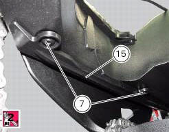
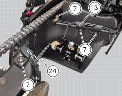
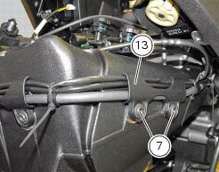
Apply the recommended threadlocker to the screws (7).
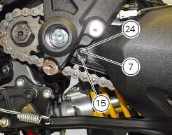
Install the lower chain guard (15) on the swingarm (8), fastening it with the screws (7): tighten the screws (7) to a torque of 4 nm +/- 10% (sect. 3 - 3, Frame torque settings).
Locate the swingarm (8) on the frame.
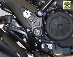
Lubricate with recommended grease the swingarm shaft (1) with the screw (3) and insert it fully home on the frame and through the brackets (36).
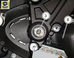
On the bike opposite side fix the swingarm shaft (1) with the screw (3) after having lubricated it with recommended grease, and fit the washer (2) between frame and swingarm.
Tighten the screw (3) to the torque of 72 nm +/- 5% (sect. 3 - 3, Frame torque settings).
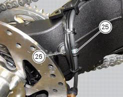
Position the rear brake hose, the rear speed sensor cable, and the rear wiring on the swingarm, by starting the screws (26) of the cable grommet (25).
Tighten the screw (26) to a torque of 8 nm +/- 10% (sect. 3 - 3, Frame torque settings).
Refit the upper chain slider (24) and the hose guide (13) and tighten the screws (7) to a torque of 4 nm +/- 10% (sect. 3 - 3, Frame torque settings).
Refit the rear wheel eccentric hub as described in chapter "refitting the rear wheel eccentric hub and rear wheel shaft" of this section.
 Overhauling the rear swingarm
Inside the swingarm (8), in correspondence with the pivot point on the frame,
there is a pair of ball bearings (10) and a
spacer (11) on the rh side, and a pair of roller bearings (6), with sealing ...
 Final drive
Circlip
Nut
Washer
Nut
Rear sprocket flange
Cush drive bush
Inner ring
Chain
Spacer
Chain cover
Screw
Nut
Lock washer
Front sprocket
Spacer
O-ring
Rear sprocket
...
Other materials:
Rear shock absorber assembly
Special screw
Screw
Nut
Grub screw
Bush (right)
Bush (left)
Screw
Sealing ring
Roller bearing
Linkage (left)
Shock absorber (rear)
Linkage (right)
Spacer
Special screw
Screw
Bush
Ball joint
Rocker arm assembly
Support
Washer
Nut
Screw
Shock absorber ...
Engine
Twin cylinder, four-stroke, 90 "l" type, longitudinal, with
deep sump die-cast crankcase.
Bore, mm: 106
Stroke, mm:
67.9
Total displacement, cu. Cm:
1198
Compression ratio:
11.5±0.5:1
Max power at crankshaft (95/1/ec), kw/hp:
119 kw/162 hp at 9,500 rpm
Max torque at crankshaf ...
Injection and ignition
Introduction
Ignition is via a single stick coil per cylinder installed in the spark plug
well. Each thermal unit is supplied by a single
injector, placed under the throttle valve. The amount of fuel injected and the
ignition advances are determined by the
control unit specifically for each c ...