
Ducati Diavel Service Manual: Wiring diagram of the hands free system
The diagram illustrates the inputs, outputs and communication lines used by the hands free system.
1I - on/off button placed on the hands free system (located below the plastic cover)
2I - on/off button placed on the bike handlebar rh side
3I - steering position micro-switch
4I - steering position micro-switch
5I - active key (signals remote transmission)
6I - passive key (it transmits signals only if leant on the antenna)
1U - electric filler plug (optional)
2U - hands free relay (it replaces the ignition switch function)
3U - steering lock actuator
1C - can line
2C - communication line via antenna (radio-frequency)
The following is the overall layout of the motorcycle network:
The following is the general electrical system diagram and pinout of the hands free system. Note that the components relative to the electric steering lock are not included as they are not integrated into the hands free module.
- Direct supply from battery - red (r);
- Hands free system ground - black (bk);
- Hands free relay coil command - red/yellow (r/y);
- Can h line - grey/black (gr/bk);
- Can l line - grey/green (gr/g);
- Input for system on/off button on handlebar - light blue (lb);
1A, 2a antenna - key communication antenna connection - blue/black (b/bk) and red/yellow (r/y); fuel tank cap coil - fuel tank cap coil command
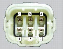
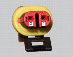
The photo shows the pinout for the hands free side connection
Location of hands free system connection
The photo shows the pinout for the hands free side antenna connection
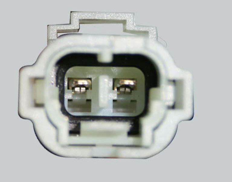
The photo shows the pinout for the hands free side electric fuel tank cap connection
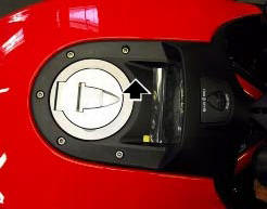
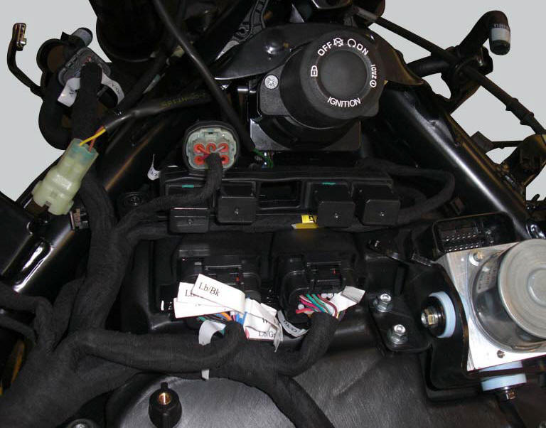
The hands free system is located in front of the fuel tank and is covered by a plastic shield. The on/off button built into the system is visible under the plastic shield. This button has the same functions as the button on the handlebar, but should only be used if the latter is not working or when starting the motorcycle without keys.
The plastic shield covering the hands free system is visible in the photo.
Note
In the usa version the door (1) is not present.
The hand free system on/off button is shown in the photo, with the plastic shield removed
The antenna used by the hands free system to communicate with the keys is placed in the document compartment under the seat.
This image shows the location of the hands free system antenna, behind the clear plexiglas windscreen
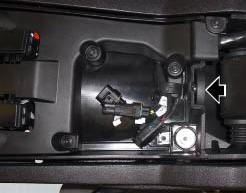
The hands free relay, which ideally replaces the function of the ignition switch of the traditional bikes, supplies +15 with key turned to on, and is positioned on its supporting bracket.
This image shows the location of the hands free relay (a). It is located on the relay supporting bracket.
Possible faults of the hands free system components
 How to reset the pin code
The pin code can be reset with the dds, i.E. It can be brought to the same
condition it was in when the bike came out
the factory. It is possible to complete the procedure with the relevant pin cod ...
 The hands free module
Introduction
The hands free module incorporates the control unit communicating with the
other nodes on the motorcycle, the on/off
button, the microswitches detecting full lock steering angle (for ...
Other materials:
Refitting the water pump
Clean the seat on the cover, any parts you intend to reuse, and the impeller
shaft. Then refit as follows.
Fit on the impeller (10) shaft the mechanical seal (9) as indicated in the
figure.
Apply specified lubricant to facilitate the insertion.
Bring the mechanical seal fully home on th ...
Timing system
Central external cover
Air filter
Horizontal cylinder timing belt cover
Screw
Filter support
Screw
Washer
Nut
Tensioner pulley assembly
Circlip
Camshaft pulley
Tensioner pin
Idler pulley assembly
Timing belt
Nut
Key
Spacer
Camshaft pulley
Driveshaft pulley ...
Beam setting
When checking beam setting, put the motorcycle upright.
Tyres should be inflated at the correct pressure and one
person should be sitting astride the motorcycle, keeping it at
right angles to its longitudinal axis. Place the motorcycle
opposite a wall or a screen, 10 meters apart from it, draw ...