
Ducati Diavel Service Manual: Removal of the front brake system

Note
For the abs front braking system, also refer to sect. 7 - 5, Abs system operating information, sect. 7 - 6, System components, sect. 7 - 7, Abs components maintenance.
Undo the special screw (3), collect the sealing washers (4), and release the front brake master cylinder assembly (1) from the pipe.
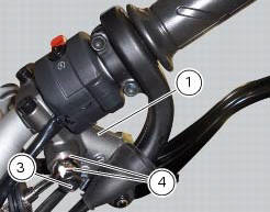
Tighten the screw (16) and slide the front brake pipe (13) from the bracket (17) on the yoke base.

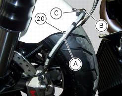
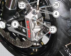
Loosen screw (c) to remove front brake hose (20) and the abs sensor cable (a) from hose clip (b).
Warning
While removing the front brake hose, if you damage the hose clip (b) you shall renew it (sect. 5 - 4, Removal of the front mudguard).
If hose is not fastened by hose clip (b), it might interfere with tyre under braking and provoke accidents.
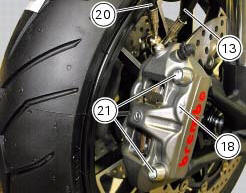
Unscrew the two fixing screws (21) of the left front brake calliper (9) to the fork leg.
Repeat the operation for the right brake calliper (18).
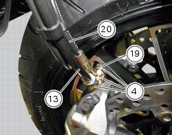
Undo the special screws (19) and (25) and collect, from both callipers, the sealing washers (4).
Detach the front brake callipers from the pipe (13) and (20).
Removal
 Maintenance operations
Warning
Brake fluid is corrosive and will damage paintwork. Avoid contact
with eyes and skin. In case of accidental contact, wash
the affected area with abundant running water and consult a doctor ...
 Removal of the brake discs
The front brake discs consist of an inner carrier, which is mounted to the
wheel, and an outer rotor. Both parts must be
changed together as a pair.
Remove the front wheel (sect. 7 - 1, Removal ...
Other materials:
Clutch lever
Lever (1) disengages the clutch. It features a dial adjuster (2)
for lever distance from the twistgrip on handlebar.
The lever distance can be adjusted through 10 clicks of the
dial (2). Turn clockwise to increase lever distance from the
twistgrip. Turn the adjuster counter clockwise to decrea ...
Setting menu
This menu is used to enable/disable and set some
motorcycle functions.
To access the "setting menu" press the button (2, fig. 14)
? for 3 seconds.
Note
When within this menu no other function can be
displayed.
Important
For safety reasons, the setting menu can only be
ac ...
Description of the clutch assembly
The clutch is disengaged by a drive unit consisting of a thrust piston (c)
accommodated inside a small cap mounted to
the generator cover. This piston (c) pushes a pushrod (b), which runs through
gearbox primary shaft and operates the Pressure plate (4)
located on top of the clutch plate pack ...