
Ducati Diavel Service Manual: Reassembling the front footrest brackets
To remove the front rh footrest bracket (6) it is necessary to remove the rear brake master cylinder reservoir (by leaving it connected to the braking system), and the rear brake lever from the bracket (sect. 7 - 4, Removing of the rear brake control).
To remove the front rh footrest bracket (6) it is also necessary to remove the rh silencer support from the bracket
(Sect. 8 - 8, Removal of the exhaust system).
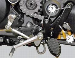
To remove the front lh footrest bracket (21) it is necessary to remove the gearchange lever from the bracket (sect. 7 - 9, Removal of the gearchange control).
Loosen the screws (7) and remove the brackets (6) and (21).
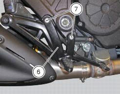
 Removing the front footrest brackets
Note
The assembly of the front footrests is described only for the right one
(2) but it is the same also for the left one.
Place the spring (4) bringing the end (a) onto the footrest (2).
Place ...
 Reassembling the front footrest brackets
To reassemble the brackets (6) and (21) carry out the removal procedure in
the reverse order; tighten the screws (7) to a
torque of 25 nm +/- 10% (sect. 3 - 3, Frame torque settings).
...
Other materials:
Refitting the air filters
Apply universal sealant in the air duct (2) and (6) groove (d).
Fit seal (7) in the groove (d) having care to place it correctly in the relevant
seat so as to avoid abnormal wrinkles.
Pull out the filter cartridge (1) from the seat in the airbox.
Position the rh air duct (2).
Start ...
Appropriate diagnosis tools
97900.0211 Dds (ducati diagnosis system) without cables
97900.0227 Power cable and diagnosis
97900.0222 Power cable and diagnosis 1060838 (measurement module)
97900.0218 Vacuum sensor
552.1.039.1A Pressure sensor
97900.0220 Pressure/vacuum tube
97900.0221 Union
...
Removal of the control unit
Loosen the screws (1) and remove the relay supporting bracket (2), disconnect
the connectors (3) and remove the control
unit (4) from the vehicle.
...