
Ducati Diavel Service Manual: Renewal of the headlight
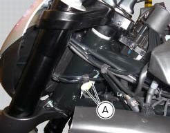
Disconnect the headlight connectors (a) from the main wiring (refer to the tables of paragraph "routing of wiring on frame", sect. 6 - 1).
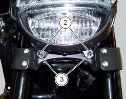
Loosen nuts (2) that fix the front optical unit to the bottom yoke, and recover the washers (3).

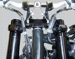
Remove the complete front optical unit by sliding it upwards and releasing it from pins (b) of the supporting bracket.

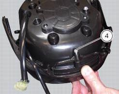
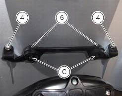
Release the headlight from the front optical unit support by loosening the screws (4) and recovering the washers (5).
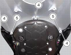
Refit the headlight on the front optical unit support, insert the spacers with collars (5) and the screws (4).
Apply the recommended threadlocker to the screws (4).
Tighten the screws (4) to a torque of 6 nm +/- 10% (sect. 3 - 3, Frame torque settings).
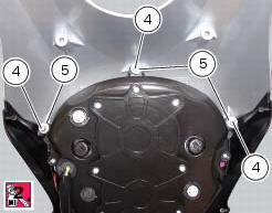

Check for the pads (6) on the supporting bracket.
Apply the recommended threadlocker to the screws (4).
Tighten the screws (4) to a torque of 6 nm +/- 10% (sect. 3 - 3, Frame torque settings).
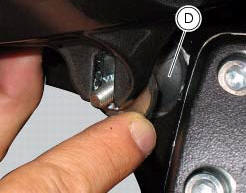
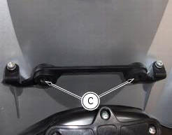
Refit the front optical unit by placing its lower part on the pads (d) and inserting the pins (b) into the eyelets (c) of the supporting bracket.
Fix the front optical applying a torque of 10 nm +/- 10% (sect. 3 - 3, Frame torque settings) to the nuts (2) with washers (3).
Reconnect the headlight connectors (a) to the main wiring (refer to the tables of paragraph "routing of wiring on frame", sect. 6 - 1).


 Changing bulbs
Changing the headlight bulbs
Before replacing a burnt out light bulb, ensure that the replacement bulb has
the same voltage and power rating as
specified for the lighting device in question (sect. ...
Other materials:
Refitting the front forks
Refit the fork legs, positioning them at the height shown in the figure
relative to the upper surface of the bottom yoke.
Warning
The difference in height between the two fork legs must be no
greater than 0.1 Mm.
Position the fork legs (5) and (6) on the yoke base (4) and on the steering ...
Hands free key (hf) not recognised
The activation of this (amber yellow) "warning" indicates that the hands free
system does not detect the active key (1,
fig.62) Near the vehicle.
Note
Check that the active key (a) is near the vehicle (and has not been lost)
or that it works properly.
...
Removal of the rear shock absorber
Loosen the screws (22) and remove the assembly (34) from the frame.
Loosen the screws (27) and remove the tank unit (s) of the shock absorber
from the support (19).
Hold the lh bush (6) and loosen the rh bush (5) to release the front side of
the shock absorber assembly.
Un ...