
Ducati Diavel Service Manual: Replacing the front phonic wheel sensor
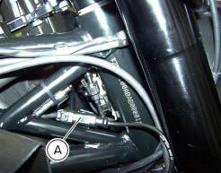
Disconnect the front abs sensor (2) connector (a) from the main electric wiring.
Open all the retainer clamps of the front abs sensor cable (2): refer to table of sect. 7 - 6, Flexible wiring/hoses positioning.

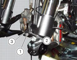
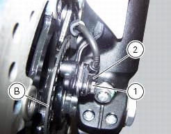
Loosen retaining screw (1) and remove the front abs sensor (2) with calibrated gasket (3).
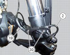
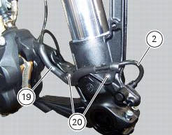
Undo the screws (20), remove the guide (19) and slide out the front abs sensor cable (2).
Before refitting, make sure that the contact parts between the front abs sensor (2) and its seat are not damaged and are perfectly clean.
Fit the new front abs sensor (2) in the relevant seat.
Insert the front abs sensor cable (2) in the guide (19) and fix it on the lh fork leg by starting the screws (20).
Tighten the screws (20).
Refit the front wheel as indicated in sect. 7 - 1, Refitting the front wheel.
Connect the connector (a) to the main wiring.
Restore all the retainer clamps of the front abs sensor cable (2): refer to table of sect. 7 - 6, Flexible wiring/hoses positioning.
Check the air gap between the front abs sensor (2) and the front phonic wheel (b) as indicated in sect. 7 - 7, Adjusting of the air-gap phonic wheel sensor.
Tighten the screw (1) to the torque of 10 nm +/- 10% (sect. 3 - 3, Frame torque settings).
 System components
Screw
Abs front speed sensor
Sealing washer
Hose grommet
Abs rear speed sensor
Abs control unit
Front pump - control unit pipe
Control unit - front callipers pipe
Rear pump - co ...
 Replacing the rear phonic wheel sensor
Disconnect the rear abs sensor (5) connector (c) from the main electric
wiring.
Open all the retainer clamps of the rear abs sensor cable (5): refer to table of
sect. 7 - 6, Flexible wiring ...
Other materials:
Removal of the front forks
Before removing the front forks, it is first necessary to remove the
following parts:
Loosen the clamp screws (1) holding the fork legs to the steering head (3).
Loosen the clamp screws (2) and (26) securing the fork legs to the bottom yoke
(4).
Withdraw the fork legs (5) and (6) downwar ...
General safety rules
Carbon monoxide
When a maintenance operation must be performed with the engine running, maker
sure that the working area is wellventilated.
Never run the engine in an enclosed space.
Warning
Exhaust fumes contain carbon monoxide, which is a poisonous gas that
can cause unconsciousness or e ...
Vehicle speed indicator
This function displays vehicle speed (km/h or mph depending on the set
measurement system).
The dashboard receives information about the actual speed and displays the
number increased by 5%.
Maximum speed displayed is 299 km/h (186 mph).
Over 299 km/h (186 mph) the display will show a s ...