
Ducati Diavel Service Manual: Replacing the rear phonic wheel sensor
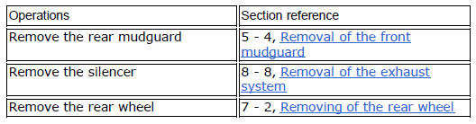
Disconnect the rear abs sensor (5) connector (c) from the main electric wiring.
Open all the retainer clamps of the rear abs sensor cable (5): refer to table of sect. 7 - 6, Flexible wiring/hoses positioning.
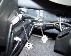
Remove the rear abs sensor (5) from its seat on the rear calliper mounting bracket (e), undoing the retaining screw (1) and collect the calibrated gasket (3).
Before refitting, make sure that the contact parts between the rear abs sensor (5) and its seat are not damaged and are perfectly clean.
Fit the new rear abs sensor (5) on its seat inserting the screw (1).
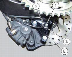
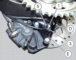
Check the air gap between the new rear abs sensor (5) and the rear phonic wheel (d) as indicated in sect. 7 - 7, Adjusting of the air-gap phonic wheel sensor.
Fix the sensor to the calliper holder bracket tightening the screw (1) to a torque of 10 nm +/- 10% (sect. 3 - 3, Frame torque settings).
Connect the connector (c) to the main wiring.
Restore all the retainer clamps of the rear abs sensor cable (5): refer to table of sect. 7 - 6, Flexible wiring/hoses positioning.


 Replacing the front phonic wheel sensor
Disconnect the front abs sensor (2) connector (a) from the main electric
wiring.
Open all the retainer clamps of the front abs sensor cable (2): refer to table
of sect. 7 - 6, Flexible wiri ...
 Removing of the abs control unit
Drain the hydraulic fluid that is inside the front and rear braking system
tubes by disconnecting them from the master
cylinder and the calliper (sect. 4 -3, Changing the brake fluid).
Disco ...
Other materials:
Reassembly of the connecting rods
Before starting, check that the crankshaft main bearing journals and big-end
journals are free of burrs or evident signs of
machining: if necessary, clean the surfaces with very fine emery cloth and oil.
Check that the grooves are in perfect condition with no signs of forcing.
Clean the cra ...
Removal of the fuel tank filler cap
Remove tank covers (sect. 5 - 2, Removal of the fuel tank fairings).
Remove hoses (8) and (15) from the filler cap assembly (10).
Open the filler cap.
Unscrew the outer screws (17) securing the ring nut to the filler cap recess.
Remove the filler cap assembly (10).
...
Cylinder compression test
Note
The on-screen icons used during this procedure are explained in a table at
the end of this section.
Engine performance is directly correlated to the pressure that can be
measured in the combustion chambers of the two
cylinders. Pressure which is too high/low or an excessive difference be ...