
Ducati Diavel Service Manual: Steering head: front fork
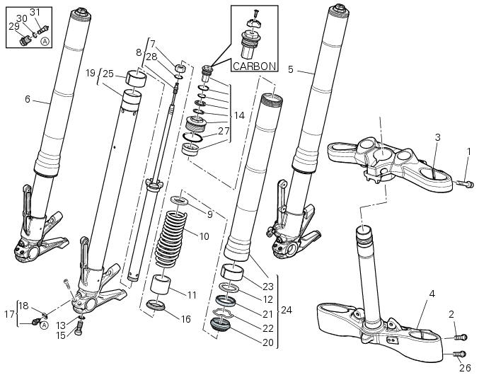
- Screw
- Screw
- Steering head
- Bottom yoke
- Left fork leg assembly
- Right fork leg assembly
- Counter nut
- Damper assembly
- Bush
- Spring
- Preload tube
- Collar
- Washer
- Top cap assembly
- Screw
- Washer
- Adjuster screw
- Special washer
- Fork tube + calliper unit
- Dust cap
- Sealing ring
- Circlip
- Upper bush
- Outer tube
- Lower bush
- Screw
- O-ring
- o-ring
- Special screw
- O-ring
- Adjuster
Spare parts catalogue
Diavel abs front forks
Diavel abs handlebar and controls
Diavel carbon abs front forks
Diavel carbon abs handlebar and controls
Important
Bold reference numbers in this section identify parts not shown in the figures alongside the text, but which can be found in the exploded view diagram.
 Fork
Fork
...
 Removal of the front forks
Before removing the front forks, it is first necessary to remove the
following parts:
Loosen the clamp screws (1) holding the fork legs to the steering head (3).
Loosen the clamp screws (2) and ...
Other materials:
Checking the idle speed
Check that the bike is provided with electronic control unit, oem intake and
exhaust systems, otherwise fit original
components.
Connect the inserts of the exhaust gas analyser code 88713.1010 To the outlets
on the exhaust pipes, using the fittings
(1).
Warning
Make sure that the thro ...
Air temperature sensor
Introduction
The engine control system on the diavel uses a sensor that measures air
temperature. This sensor has a resistance of
ntc type (negative temperature coefficient), that reduces its own value when the
temperature increases. The air
temperature sensor allows the engine control unit t ...
Removal of the fuel tank
On the usa version remove the canister filter as indicated in sect. 8 - 10,
"Removal of the evaporative emissions
canister".
Loosen and remove the front retaining screw (4)
Remove the flange cover (a) by loosening the screws (b), disconnect the
quick-release fittings (c) from the fl ...