
Ducati Diavel Service Manual: Throttle valve actuator motor relay
Introduction
The throttle valve actuator motor is powered by the engine control unit. The engine control unit receives the necessary power from a specific relay.
Component assembling position
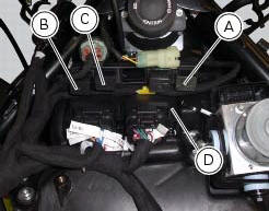
A injection relay; b etv relay (throttle valve actuator motor), c radiator fan relay, d engine control unit.
Connection wiring diagram
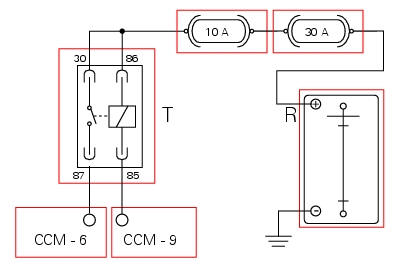
Ccm engine control connection, t throttle valve actuator motor relay. 85 Throttle valve actuator motor relay activation, light blue/green - lb/g, 87 ecu power input for throttle valve actuator motor, red/brown r/bn, 30 and 86 red/purple - r/v, r battery positive (+30).
In the event of fault
In the event of a throttle valve actuator relay fault, the ecu cuts motor power and the throttle valves close (see chapter operating principle and characteristics of the ride-by-wire system in this section).
Fault codes generated and possible correlated faults
Fault codes generated by the engine control unit and displayed by the dds (etv relay diagnosis):
- Throttle valve actuator motor relay malfunction (no specific fault indicated by dds): check integrity of the fuses, electrical circuit and electrical connections and check relay function. After removing from its mounting, apply 12 v power to pin 85 and pin 86 and check that pin 87 and pin 30 close (continuity between pins).
Note
Check integrity of electric circuit - short-circuit to vdc = with dashboard on, using a voltmeter, a voltage is measured between the wire tested and ground.
Check integrity of electric circuit - short-circuit to ground = with the battery cables disconnected, using an ohmmeter, continuity is detected between the wire tested and ground.
Check integrity of electric circuit - open circuit = with the battery cables disconnected, using an ohmmeter, no continuity is detected between the two ends of the wire tested.
The dashboard service display shows the error "etv relay" (throttle valve actuator motor relay) and the eobd warning light activates.
Possible correlated faults: the engine does not start, cuts out or remains running at idle speed and will not accelerate.
Check:
- Integrity of fuses.
- Relay function.
The throttle valve actuator motor may be actuated into one of the three preset positions (0%, 50%, 100%) using the dds. During motor actuation, the throttle valve actuator motor relay is driven.
If none of the tests described above identify the problem and the throttle valve actuator relay is in proper working order, contact ducati.
Component replacement methods
No special measures are necessary in order to replace the throttle valve actuator motor relay.
 Injection relay
Introduction
The fuel pump, injectors and ignition coils are all powered via the injection
relay. The relay also sends voltage to the
engine control unit, which enables activation of the relay its ...
 Starter motor relay
Introduction
When the rider presses the start button, with all the safety conditions
required to enable engine start met, the engine
control unit enables the relay that activates the starter motor ...
Other materials:
Ignition coils
Introduction
The engine control system of the diavel includes two ignition coils: one for
the horizontal cylinder and one for the vertical
cylinder. These coils are installed directly in the spark plug wells. A diode is
installed on the secondary winding inside the
coil, which prevents the un ...
Checking the fuses
The main fuse box (1) and the secondary one (2) are located in the tool tray;
to reach the fuse box remove the seat as
specified under sect. 5 - 3 "Removal of the seat".
The fuses are accessed by removing the cover, which shows the ampere ratings and
mounting locations.
For ampere ratings ...
Operating principle of dtc
The bbs receives the front and rear speed information from the abs over the
can. Then, the bbs sends the vehicle speed
information to be displayed on the dashboard over the can.
If the tangential speed of the rear wheel exceeds the tangential speed of the
front wheel by a given percentage, t ...