
Ducati Diavel Owners Manual: Engine on/off
 Warning
Before starting the engine, become familiar with the controls you will need to use when riding (page 99).
 Warning
Never start or run the engine indoors. Exhaust gases are toxic and may lead to loss of consciousness or even death within a short time.
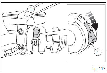
In the presence of the active or passive key, perform a key- on (turning on the "hands free" system and all on-board electronic devices) by pushing the red switch (1, fig. 117), On the right side of the handlebar, downward.
The instrument panel on handlebar will perform the initialisation and will control the onboard systems, turning on all lights in sequence, from outside to inside, for a few seconds.
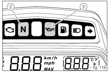
After this control, only the green light (2, fig. 118) And the red
light  (3) must remain on.
 Warning
The side stand must be fully up (in a horizontal position) as its safety sensor prevents engine start when down.
After key-on, but with the engine not yet started, the system will perform a key-off automatically if the presence of the active key is not detected within 10 seconds.
 Note
Note
It is possible to start the engine with side stand down and the gearbox in neutral. When starting the bike with a gear engaged, pull the clutch lever (in this case the side stand must be up).
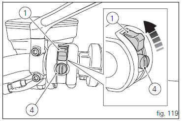
Move the red switch (1) up to uncover the black button (4, fig. 119).
Push the button (4) to start the engine.
 Important
Do not rev up the engine when it is cold. Allow some time for the oil to warm up and reach all points that need lubricating.
The red oil pressure warning light should go out a few seconds after the engine has started.
The engine will shut off by turning the red key (1, fig. 119) On the handlebar to run off.
 Note
Note
To turn on the "hands free" system and all electronic onboard systems, refer to page 100 "hands free system".
 Pre-ride checks
Warning
failure to carry out these checks before riding, may
lead to motorcycle damage and injury to rider and passenger.
Before riding, perform a thorough check-up on your bike as
follows:
Fuel ...
 Moving off
Disengage the clutch by squeezing the clutch lever.
Push down the gear change lever firmly with the tip of
your foot to engage first gear.
Raise the engine revs by turning the throttle twistg ...
Other materials:
Tank filler plug
Note
To open or close the tank filler plug using the active
key, set the metal part in the middle position, as shown on
page 86.
Opening
Lift the cover (1, fig. 100) And insert the active or passive key
into the lock. Give the key a 1/4 turn clockwise to unlock.
Lift the plug (2, fig. 101) ...
Removing of the front sprocket
Undo the screws (11) and remove the chain cover (10).
Loosen the chain (sect. 4 - 3, Adjusting the chain tension).
Remove the chain with the tool code 88713.1344.
The tool is composed of a holder (a), punch (b), body (c) and two wrenches (d)
and (e).
Fit the link to be opened into th ...
Battery voltage indicator (battery)
This function describes the battery voltage indicator.
To access the function it is necessary to view the "setting" menu page 48, using
button (1, fig. 14) ?"" or (2, fig.
14) ?" " select the "battery" function
and press the reset
button (12, fig. 12 ...