
Ducati Diavel Service Manual: Throttle valve operation engine
Introduction
The electric motor actuating the throttle valve for the vertical cylinder is mounted on the throttle body of the diavel, while a link rod connects the vertical cylinder throttle valve to the horizontal cylinder throttle valve. In the electric motor, the throttle valve position sensor (tps) is integrated.
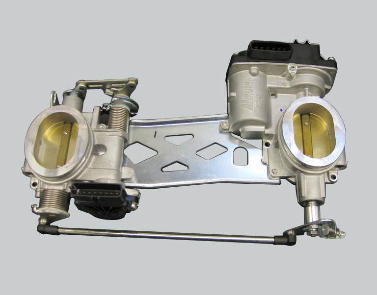
The electric motor, which also incorporates the throttle valve position sensor (tps), is visible on the right, on the throttle body. The accelerator position sensor (aps) is visible on the left.
Component assembling position
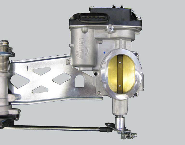
The electric motor, which also incorporates the throttle valve position sensor (tps), is visible on the right, on the throttle body. The accelerator position sensor (aps) is visible on the left.
Component assembling position
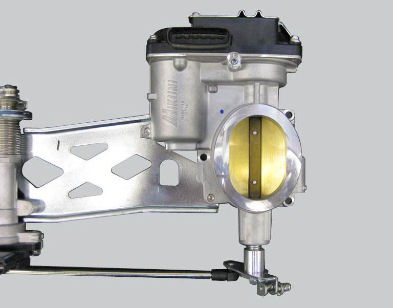
The image shows the throttle valve actuator motor. Inside of it, it is also placed the throttle valve position sensor (tps).
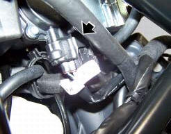
Location of electric connection for throttle valve actuator motor - tps (throttle valve position sensor).
Connection wiring diagram
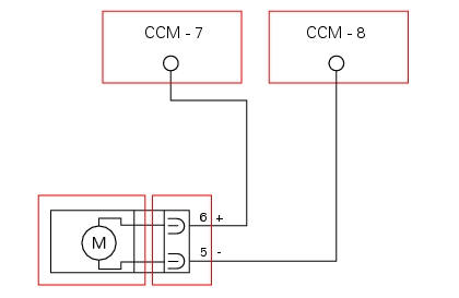
Ccm engine control connection, m throttle valve actuator motor. 5 Light blue/red - lb/r, 6 light blue/black- lb/bk.
In the event of fault
In the event of a throttle valve actuator fault, motor power is cut off and the throttle valves close (see chapter relative to ride-by-wire system).
Fault codes generated and possible correlated faults fault codes generated by the engine control unit and displayed by the dds (etv motor diagnosis):
- Open circuit (feedback error): check integrity of electric circuit and electrical connections.
- Short circuit to vdc: check integrity of electric circuit and electrical connections.
- Short circuit to ground: check integrity of electric circuit and electrical connections.
Note
Check integrity of electric circuit - short-circuit to vdc = with dashboard on, using a voltmeter, a voltage is measured between the wire tested and ground.
Check integrity of electric circuit - short-circuit to ground = with the battery cables disconnected, using an ohmmeter, continuity is detected between the wire tested and ground.
Check integrity of electric circuit - open circuit = with the battery cables disconnected, using an ohmmeter, no continuity is detected between the two ends of the wire tested.
The dashboard service display shows the error "etv motor" (throttle valve actuator motor) and the eobd warning light activates.
Possible correlated faults: the engine does not start, cuts out or remains running at idle speed and will not accelerate.
Check:
- Functionality of throttle valve actuator motor relay (see paragraph "throttle valve actuator relay")
The throttle valve actuator motor may be actuated into three preset positions (0%, 50%, 100%) using the dds.
If none of the tests described above identify the problem and the throttle valve actuator is in proper working order, contact ducati.
Component replacement methods
The throttle valve actuator motor incorporates the throttle valve position sensor (tps) and cannot be replaced as an individual component. In case it brakes down it will be necessary to fit a new throttle body (refer to sect. 6 - 8, Operating principle and characteristics of the ride-by-wire system). After replacement of the throttle body, reset the self-adaptive parameters relative to carburation with the dds. Adjust the cables connecting the throttle grip to the throttle grip position sensor.
 Injectors
Introduction
The injectors used on the diavel are top feed units, meaning that fuel is fed
into the top of the injector itself. The
injectors contain a winding which raises a needle when electrica ...
 Engine start button
Introduction
The engine start button is located on the right hand handlebar switchgear set
and is used to turn the engine on.
Component assembling position
The engine start button is included ...
Other materials:
Refitting the clutch transmission unit
Position pipe (4) on the clutch slave cylinder (r).
Position the two seals (19) and tighten the screw (18) to a torque of 23 nm +/-
10% (sect. 3 - 3, Frame torque settings).
Refit the bleed valve (17) and the dust gaiter (16).
To position the pipe retaining clamps (4) refer to the table on ...
Adjusting the steering head bearings
Note
To adjust the steering bearing clearance, follow what is described in
sect. 4 - 3, Adjusting the steering head bearings.
If the problems found are not solved, check the wear of steering bearings (6)
and replace them, if necessary, as described
in paragraph "removal of the steering head c ...
Recovery procedure in the event of electric steering lock fault
If any fault occurs during activation of the electric steering lock: for
example, if the pin jams, if the handlebar is moved
while the pin is deployed or if there is excessive strain on the electric pin
actuator motor, the electric steering lock is
automatically disengaged and the hands free s ...