
Ducati Diavel Service Manual: Wiring diagram colour codes
B blue
Bk black
Bn brown
G green
Gr grey
Lb light blue
O orange
P pink
R red
V violet
W white
Y yellow
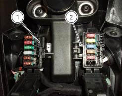
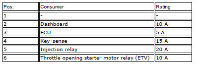
Rear left fuse box (1) key
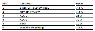
Rear right fuse box (2) key
 Key to wiring diagram
Right-hand handlebar switch
Immobilizer
Hands free relay
Hands free
Front fuse box
Right fan
Left fan
Fan relay
Fuel pump relay
Ride-by-wire relay (etv)
Injection control unit ( ...
 Routing of wiring on frame
The routing of the wiring has been optimised to ensure the minimum
obstruction.
Each section is designed to prevent interference with parts that might damage
wires or cause operating failures w ...
Other materials:
Removing of the rear brake control
Warning
The brake master cylinder manufacturer advises against servicing the
brake master cylinder due to the safety critical
nature of this component.
Incorrect overhaul can endanger the rider and passenger.
Maintenance operations on these units are limited to renewal of the following
par ...
Coolant temperature
This function indicates coolant indication state.
The temperature unit of measure can be selected (C or f).
The reading is indicated as follows:
if the reading is between - 39C and +39C "lo" is shown flashing on the
dashboard (steady);
if the reading is between +40C and +120C it appears on t ...
Limited liability
The liability of ducati under this emission control systems
warranty is limited solely to the remedying of defects in
material or workmanship by an authorized ducati motorcycle
dealer at its place of business during customary business
hours. This warranty does not cover inconvenience or l ...