
Ducati Diavel Service Manual: Routing of wiring on frame
The routing of the wiring has been optimised to ensure the minimum obstruction.
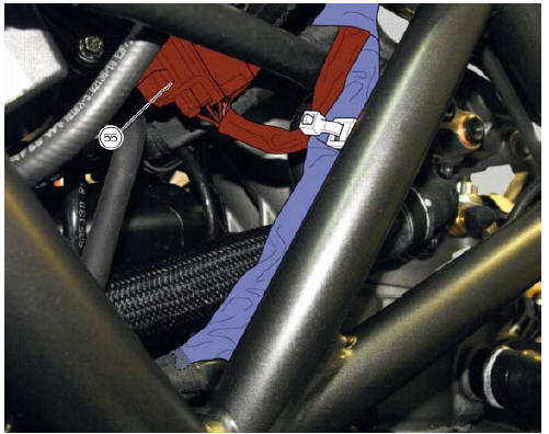
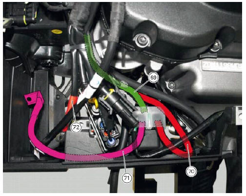
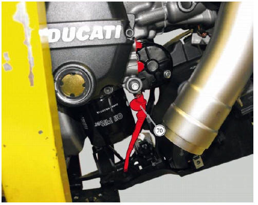
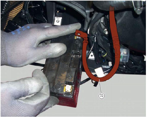
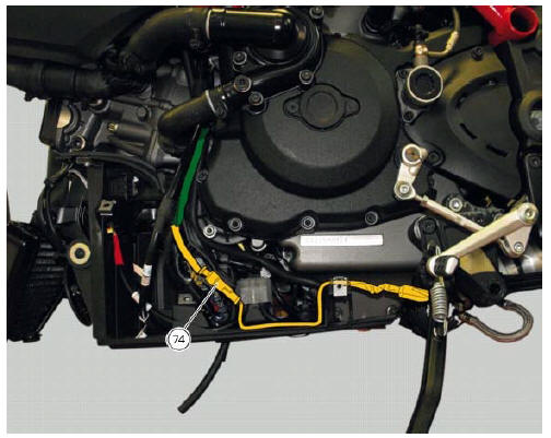
Each section is designed to prevent interference with parts that might damage wires or cause operating failures when riding. The plates on the following pages show the origins ("0" points) for correct re-routing of wiring and the locations of cable ties.
Each figure includes references to the plates showing the wiring routing or the item to which it must be connected.
Table a
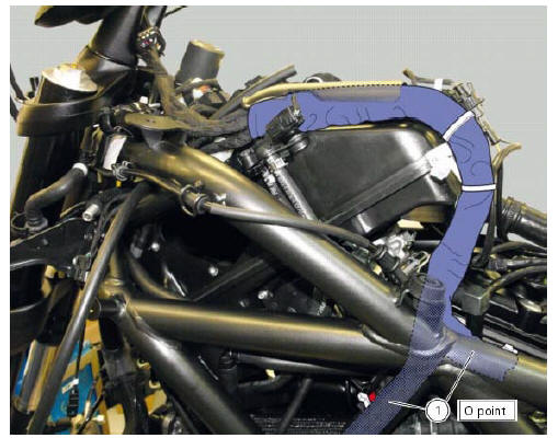
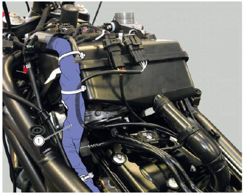
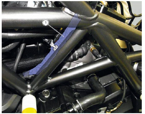
Table b
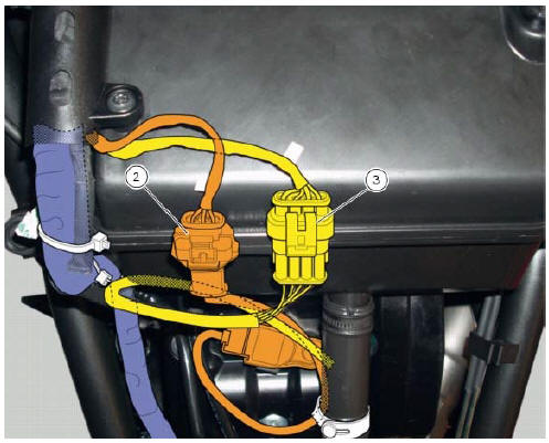
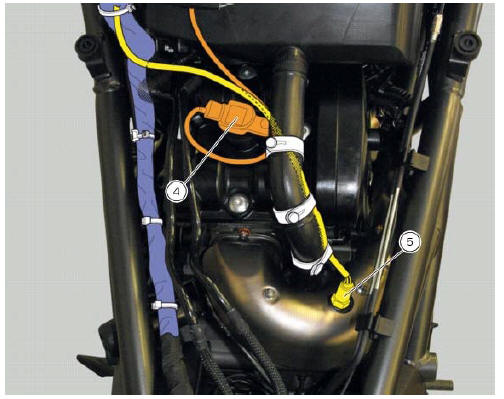
Table c
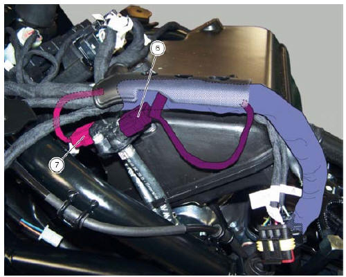
Table d
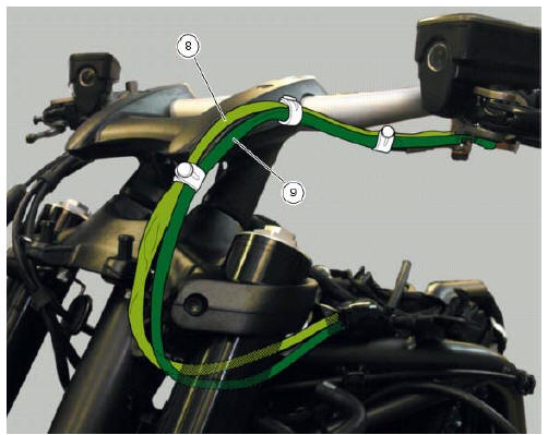
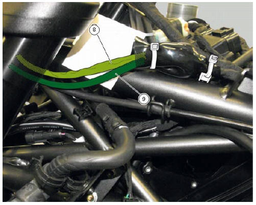
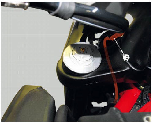
Table e
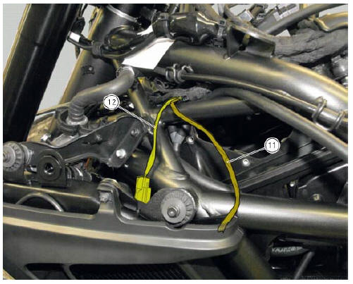
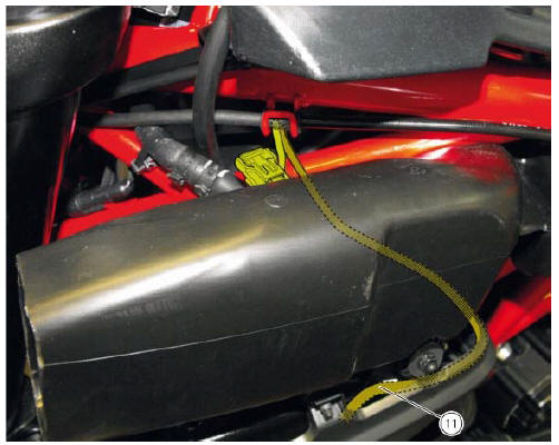
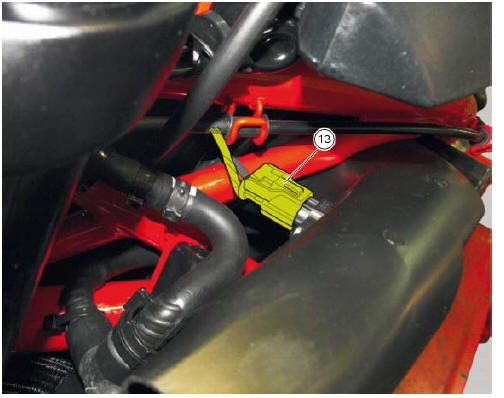
Table f
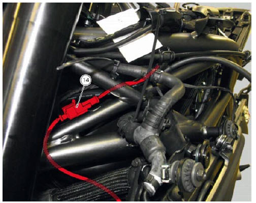
Table g
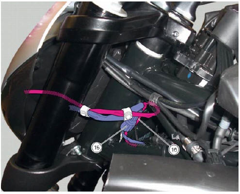
Table h
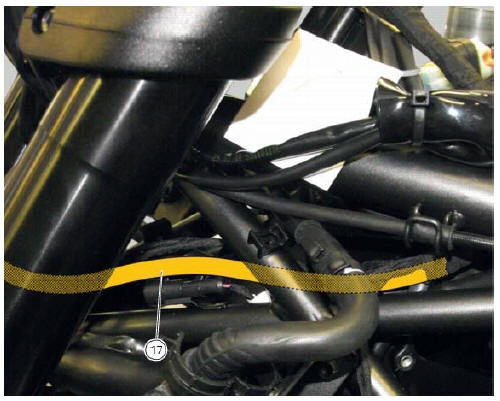
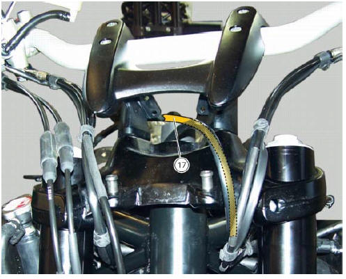
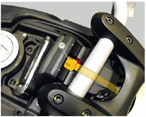
Table j
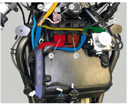
Table k
Table l
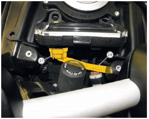
Table m
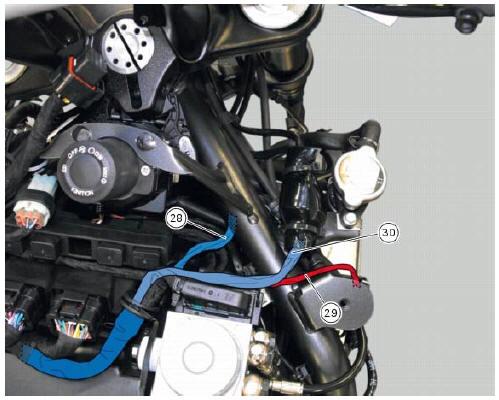
Table n
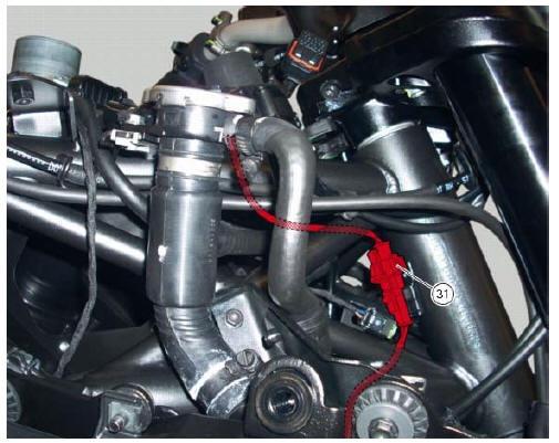
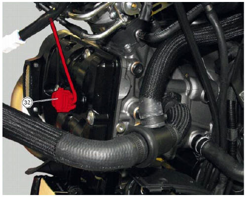
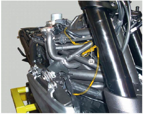
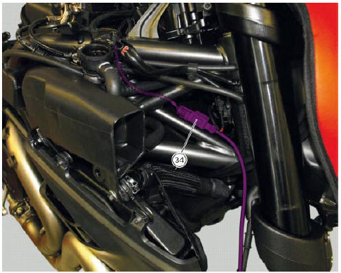
Table o
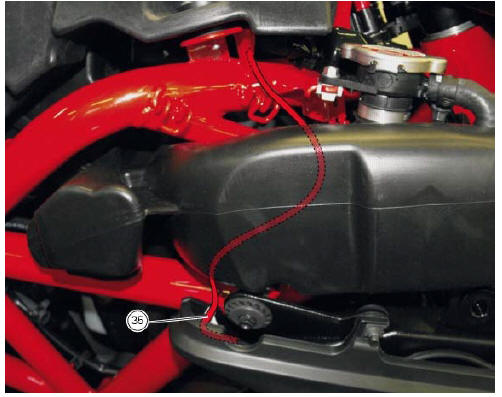
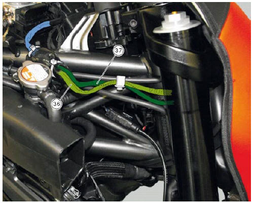
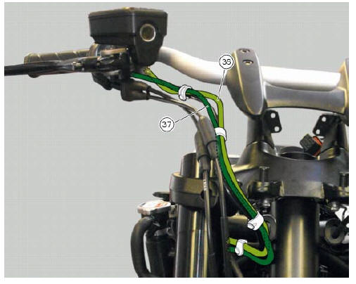
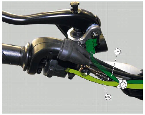
Table p
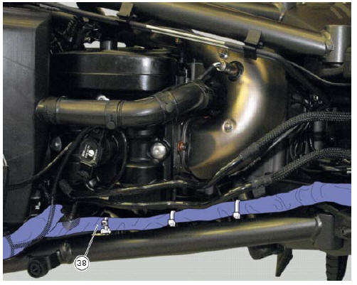
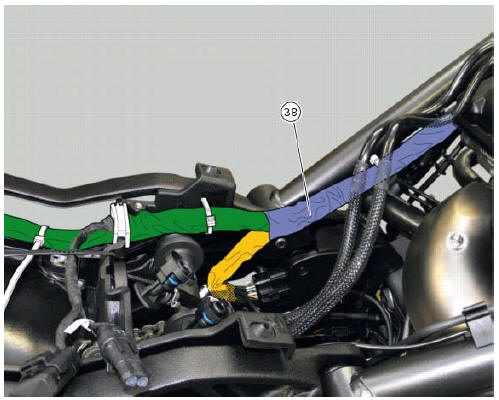
Table q
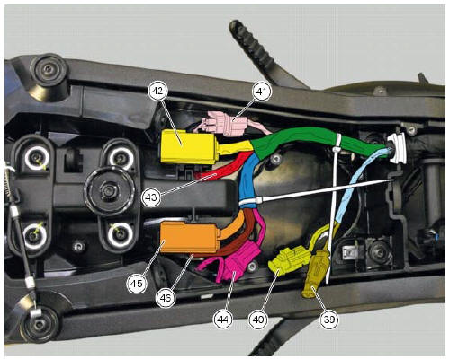
Table r
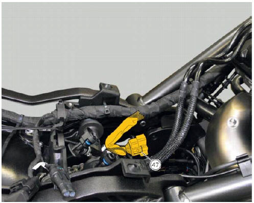
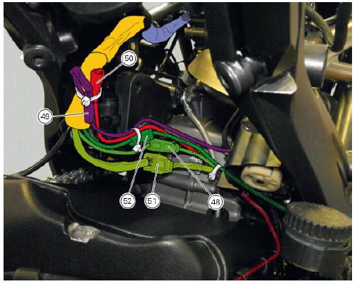
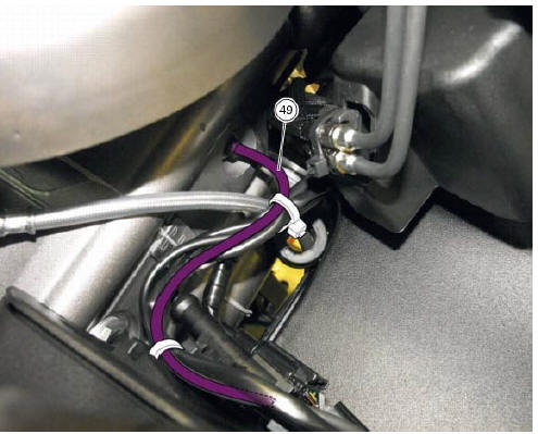
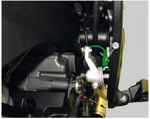
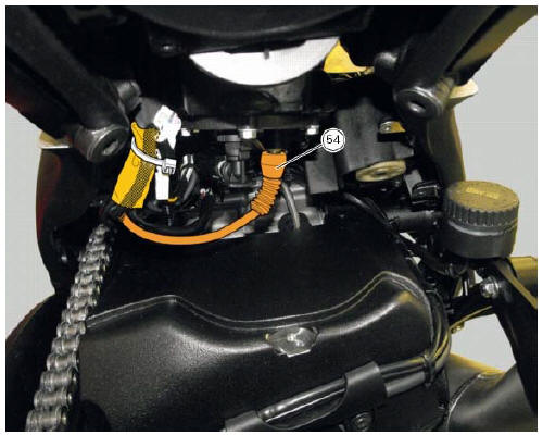
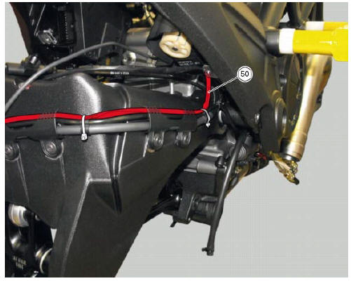
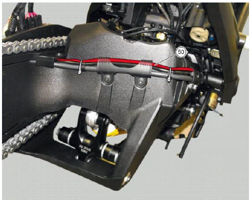
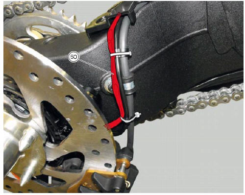
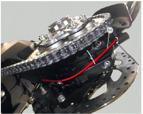
Table s
Table
t
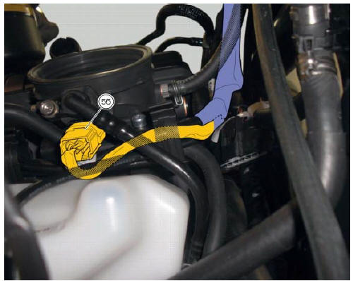
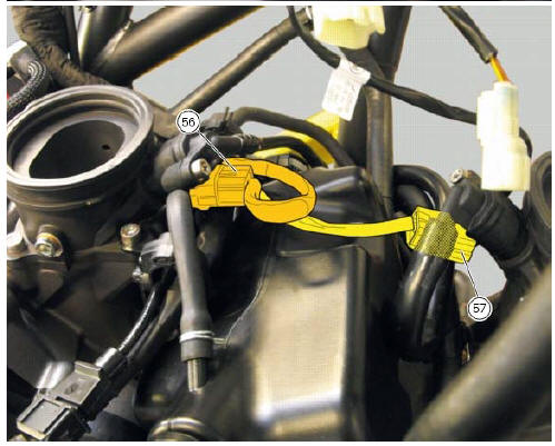
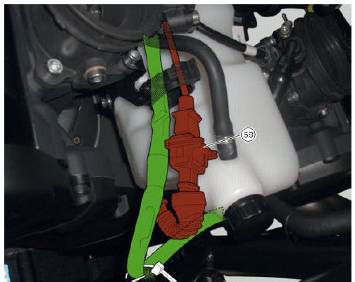
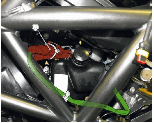
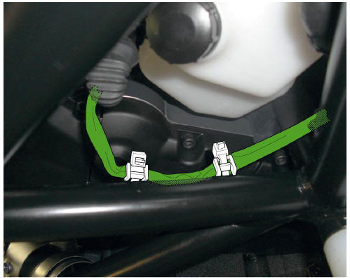
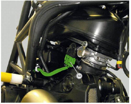
Table u
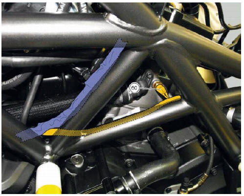
Table v

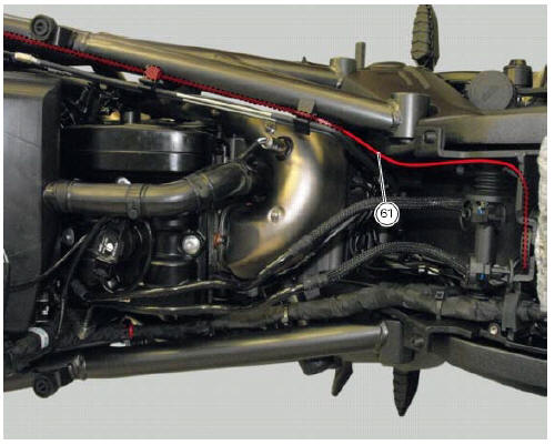
Table w
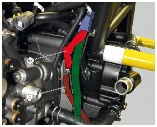
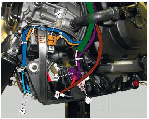
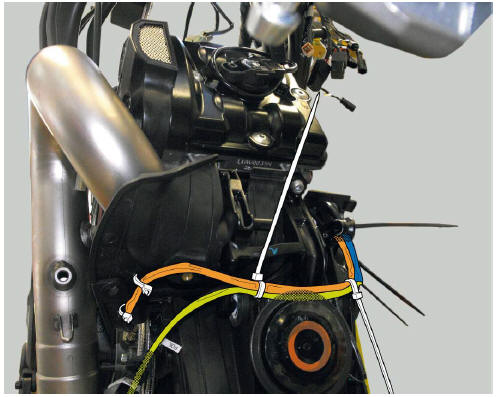
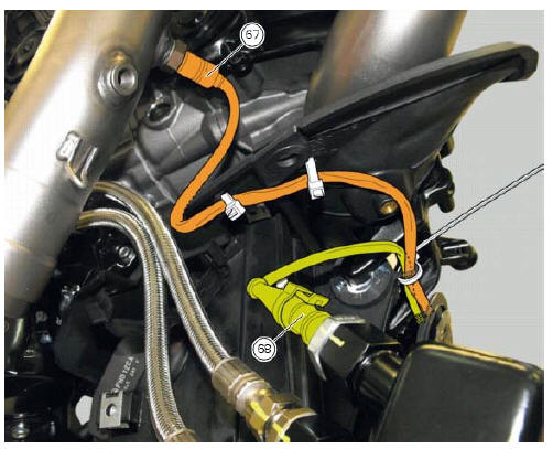
Table x

 Wiring diagram colour codes
B blue
Bk black
Bn brown
G green
Gr grey
Lb light blue
O orange
P pink
R red
V violet
W white
Y yellow
Rear left fuse box (1) key
Rear right fuse box (2) key
...

Other materials:
Abs disabled information not displayed
Fault codes
Dds: displays a fault code described in the description of the abs system.
Dashboard: no fault code displayed.
Wiring diagram
Checks
The abs fault indicator indicates the occurrence of one or more faults in the
antilock brake system, or if the system itself
has been disable ...
Inspection of the gear selector forks
Visually inspect the gear selector forks. Bent forks must be renewed as they
may lead to difficulties in gear changing or
may suddenly disengage when under load.
Use a feeler gauge to check the clearance of each fork in its gear groove.
If the service limit has been exceeded, check whether ...
Abs system operating information
The response of the system is based on the analysis of the speed signals for
front and rear wheels; the system is
automatically deactivated if either of these signals is missing.
Note
In the event of the abs control unit detecting a fault in the abs
electronic management system, it activates ...