
Ducati Diavel Service Manual: Refitting the water pump
Clean the seat on the cover, any parts you intend to reuse, and the impeller shaft. Then refit as follows.
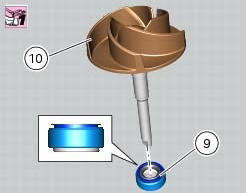
Fit on the impeller (10) shaft the mechanical seal (9) as indicated in the figure.
Apply specified lubricant to facilitate the insertion.
Bring the mechanical seal fully home on the impeller.
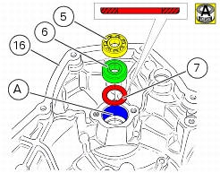
Grease the seat (a) of the bearings for the impeller on the generator cover (12).
Insert spacer (7) fully home into the generator cover by orienting it so that the round edge is faced down.
Fit bearing (6) completely into the spacer.
Fit bearing (5) completely on the bearing (6).
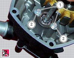
Fit the washers (2) on the screws (1).
Orient the washers so that the knurled side is faced to the screw head.
Apply recommended threadlocker to the screws.
Fit the two screws (1) and tighten them to a torque of 10 nm (min. 9 Nm - max. 11 Nm) (sect. 3 - 3, Engine torque Settings).
Turn the cover upside down.
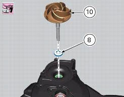
Introduce the counterface (8) completely into the generator cover.
The counterface must be oriented so that the white side is faced upwards.
Apply specified lubricant to facilitate the counterface insertion.
Clean the counterface from exceeding lubricant.
Install the water pump impeller (10) and bring completely against the counterface.
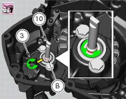
Use the special tools to install the snap ring (3) into the proper groove (b), on the impeller (10) shaft, as shown in figure.
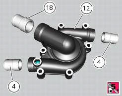
If previously removed, apply specified threadlocker on the threads of the water pump delivery unions (4).
Fit the unions on the water pump cover (12) and tighten them to a torque of 25 nm (min. 23 Nm - max. 27 Nm) (sect. 3 - 3, Engine torque settings).
Apply recommended threadlocker on the thread of the water pump intake union (18).
Fit the union on the water pump cover (12) and tighten it to a torque of 25 nm (min. 23 Nm - max. 27 Nm) (sect. 3 - 3, Engine torque settings).
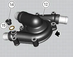
If previously removed, insert washer (14) into the plug of the water pump cover (15).
Fit the plug on the water pump cover (12) and tighten it to a torque of 20 nm (min. 18 Nm - max. 22 Nm) (sect. 3 - 3, Engine torque settings).
Clean the mating surfaces thoroughly on the pump cover and on the alternator-side crankcase cover.
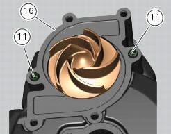
If previously removed, install the two centring bushes (11) completely into the generator cover.
Apply a bead of fluid gasket on the generator cover (16).
Insert the fixing screws (13) and (18) of the cover.
Tighten the screws (13) to a torque of 10 nm (min. 9 Nm - max. 11 Nm) (sect. 3 - 3, Engine torque settings).
Tighten the screws (13) to a torque of 13.5 Nm (min. 12.5 Nm - max. 14.5 Nm) (sect. 3 - 3, Engine torque settings) following the indicated sequence.
Refit the components removed in the procedure.
![]()
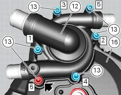
 Removal of the water pump
Note
For clarity, the figures show the engine removed from the frame.
Loosen and remove the water pump cover (12) fixing screws (13) to the
generator cover (16).
Remove the water pump cover ...

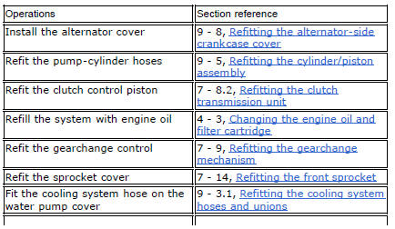
Other materials:
Refitting the rear mudguard
Place the rear mudguard (8) on the swingarm, fitting the screws (9) with
recommended threadlocker.
The screw (9) in the bottom hole of the rear mudguard (8) must be installed with
the washer (r).
Tighten the screws (9) to a torque of 5 nm +/- 10% (sect. 3 - 3, Frame torque
settings).
...
Indicator air - air temperature
This function shows the external temperature.
Display limits: -39C ÷ +124C
In the event of a sensor fault (-40C,+125C or
disconnected), a string of dashes "- - -" (not flashing) is
displayed and the "engine/vehicle diagnosis - eobd" light
(7, fig. 4) Comes on.
N ...
Indicator cons. - Instantaneous fuel consumption
This function indicates the "instantaneous" fuel consumption.
The calculation is made considering the quantity of fuel used and the distance
travelled during the last second. The datum
is expressed in "l / 100" (litres / 100 km); it is possible to change the units
of measurement for "consump ...