
Ducati Diavel Service Manual: Timing system
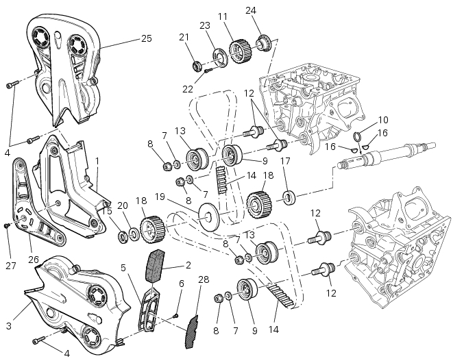
- Central external cover
- Air filter
- Horizontal cylinder timing belt cover
- Screw
- Filter support
- Screw
- Washer
- Nut
- Tensioner pulley assembly
- Circlip
- Camshaft pulley
- Tensioner pin
- Idler pulley assembly
- Timing belt
- Nut
- Key
- Spacer
- Camshaft pulley
- Driveshaft pulley spacer
- Spacer
- Nut
- Screw
- Washe
- Spacer flange
- Vertical cylinder belt external cover
- Central protection
- Screw
- Mesh
Spare parts catalogue
Diavel abs Timing system
Diavel abs cylinder head: timing system
Diavel carbon abs timing system
Diavel carbon abs cylinder head: timing system
Important
bold reference numbers in this section identify parts not shown in the figures alongside the text, but which can be found in the exploded view diagram.
Note
For clarity, the figures show the engine removed from the frame.
To work with the engine installed, first proceed as follows:

Note
Remove also any parts which may impede the procedure in any way.
- Removal of the timing belt covers
- Removal of the movable tensioner/timing belt
- Removing of the cylinder head pulley/fixed tensioner
- Disassembly of the camshaft pulleys
- Removing the timing belt driveshaft pulleys
- Refitting the timing belt driveshaft pulleys
- Refitting the idler and tensioner pulley mounting studs
- Reassembly of the timing pulleys
- Refitting the cylinder heads pulleys/fixed tensioners
- Refitting the timing belts
- Refitting the timing covers
 Checking the engine timing
Set the engine to the configuration described for the "checking and adjusting
the valve clearances", previously indicated.
Install tool 88765.1188 (G) in the spark plug bore to determine the ...
 Removal of the timing belt covers
Loosen the screws (4) securing the central external cover (1) and remove it
from the central side.
Undo the fixing screws (4) of the external cover (25) and remove it from the
vertical therma ...
Other materials:
Coolant temperature
This function indicates coolant indication state.
The temperature unit of measure can be selected (C or f).
The reading is indicated as follows:
if the reading is between - 39C and +39C "lo" is shown flashing on the
dashboard (steady);
if the reading is between +40C and +120C it appears on t ...
Description of the clutch assembly
The clutch is disengaged by a drive unit consisting of a thrust piston (c)
accommodated inside a small cap mounted to
the generator cover. This piston (c) pushes a pushrod (b), which runs through
gearbox primary shaft and operates the Pressure plate (4)
located on top of the clutch plate pack ...
Stored lap erase function
This function erases the stored laps.
To access the function it is necessary to view the "setting" menu", using
buttons (1) "s" or (2) "t" select the "lap"
function and press the reset button (3) to enter the following page.
Use button (1) "s" or (2) "t" to select "lap data" indication and ...