
Ducati Diavel Owners Manual: Adjusting the position of the gearchange and rear brake pedals
The position of the gearchange and rear brake pedals in relation to the footrests can be adjusted to suit the requirements of the rider.
Adjust the pedals as follows:
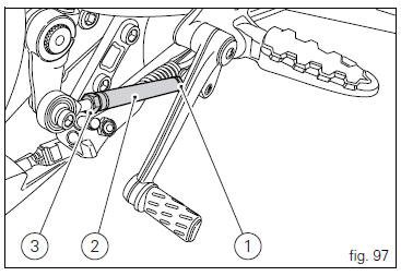
Gear change pedal (fig. 97) Hold the linkage (1) and slacken the lock nuts (2) and (3).
 Note
Note
Nut (2) has a left-hand thread.
Fit an open-end wrench to hexagonal element of linkage (1) and rotate until setting pedal in the desired position.
Tighten both check nuts onto linkage.
Rear brake pedal
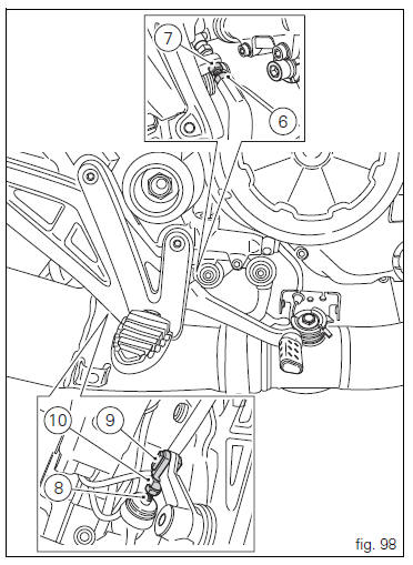
Loosen counter nut (7).
Turn pedal stroke adjusting screw (6) until pedal is in the desired position.
Tighten the counter nut (7).
Operate the pedal by hand to check that there is 1.5 To 2 mm of freeplay before the brake bites.
If not, adjust the length of the master cylinder pushrod as follows.
Slacken off the counter nut (10) on the pushrod.
Screw the pushrod (8) into the front fork (9) to increase the freeplay, or screw it out to reduce it.
Tighten the counter nut (10) and recheck the pedal freeplay.
 Gear change pedal
When released, the gear change pedal (1, fig. 96)
Automatically returns to rest position n in the centre. This is
indicated by the instrument panel light n (2, fig. 4) Coming on.
The pedal can be ...

Other materials:
Bleeding of the abs hydraulic system
If some "sponginess" is detected on the brake control, due to air bubbles in
the system, bleed the system, as indicated in
sect. 4 - 3, Changing the brake fluid.
Before bleeding a brake pump, move back the calliper pistons, as indicated in
(sect. 4 - 3, Changing the brake fluid) to Drain in ...
Removal of the swingarm
Before removing the parts in question, you must first carry out the following
operations:
Remove the rear wheel eccentric hub as described in chapter "removal of the
rear wheel eccentric hub and rear wheel
shaft" of this section.
Loosen screws (7) and remove the hose grommets (13), (15) ...
Brakes
Separate-action anti-lock brake system operated by hall-type
sensors mounted to each wheel, with phonic wheel
detection: abs can be disabled.
Front
Semi-floating drilled dual disc.
Braking material:
steel.
Carrier material:
aluminium.
Disc diameter:
320 mm.
Hydraulically operated ...