
Ducati Diavel Service Manual: Rectifier-regulator
The rectifier (1) is placed in the electrical components compartment.
The rectifier/regulator consists of an aluminium casing containing the diodes that rectify the current produced by the alternator. It also contains an electronic device that regulates the current supplied by the alternator in accordance with battery voltage.
If the battery is drained, the current has the value necessary to restore optimum operating conditions of the battery. In contrast, if the battery is fully charged, the current value will be lower.
Note
Control the charger current by using the dds diagnosis instrument (sect. 6 - 11, Diagnostic instruments).
Removal of the regulator 
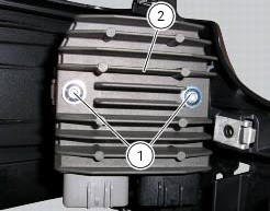
Undo the two fixing screws (1) of the voltage regulator (2) and remove it together with them.
Important
Do not disconnect the battery cables when engine is running because this would cause irreparable damage to the regulator.

Refitting the regulator
Position the regulator (1) on the support.
Tighten the screws (1) to a torque of 10 nm +/- 10% (sect. 3 - 3, Frame torque settings).
Important
Do not disconnect the battery cables when engine is running because this would cause irreparable damage to the regulator.
Regulator fuse
The 30 a fuse is located inside the solenoid starter in the electrical components compartment.
Remove the fuse cap (a) to reach it.
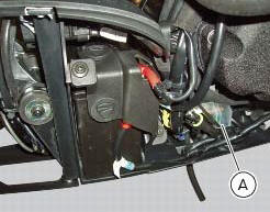
A blown fuse can be identified by breakage of the inner filament (b).
Important
To avoid possible short circuits, replace the fuse in key off condition.
Warning
Never use a fuse with a rating other than the specified value. Failure to observe this rule may damage the electric system or even cause fire.
 Alternator
It is equipped with a 12 v, 430 w generator, consisting of a fixed element
(stator, a) located on the generator cover and
of a movable element (rotor, b) fixed to the crankshaft.
Note
To chec ...
 Electric starting system
Note
The references of the elements listed below are those of the "wiring
diagram", sect. 6 -1.
Electric starting system
The key components of the electric starting system are a solenoid (6) and ...
Other materials:
Scheduled maintenance chart
Operations to be carried out by the dealer
List of operations to be performed at 1000 km
Reading of the error memory with dds on the engine control units, vehicle and
abs
Change the engine oil
Change the engine oil filter
Check the indicators and lighting
Check the safety devices (side stand ...
Overhaul of the connecting rods
Make the following dimensional checks on the connecting rods:
Clearance with gudgeon pin on assembly.
In the event of excessive wear (sect. 3 - 1.1, Crankshaft), replace the
connecting rod.
The small end bushing must be in good condition and firmly driven into its seat.
Check for para ...
Tips for use on the track
We recommend level 8 be used for a couple of full laps (to
allow the tyres to warm up) in order to get used to the
system. Then try levels 7, 6, etc., In succession until you
identify the dtc intervention level that suits you best (always
try each level for at least two laps to allow the tyres t ...