
Ducati Diavel Owners Manual: Adjusting the rear shock absorber
The rear shock absorber has external commands that enable you to adjust the setting to suit the load on the motorcycle.
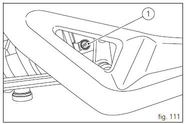
The adjuster (1, fig. 111) Located on the lower connection holding the shock absorber to the swingarm adjusts the damping during the rebound phase (return).
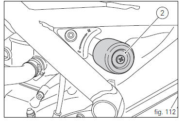
The knob (2, fig. 112), Located on the left side of the motorcycle, adjusts the preload of the shock absorber external spring.
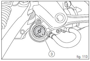
The knob (3, fig. 113) Located on the expansion reservoir of the shock absorber adjusts the damping during the compression phase.
Turning the adjusters (1) or the knobs (2) and (3) clockwise to increase preload damping; they decrease turning them in the opposite direction.
Standard setting; from fully closed (clockwise) loosen: adjuster (1, fig. 111) By 12 clicks; knob (2, fig. 112) Fully open (counter clockwise); adjuster (3, fig. 113) By 25 clicks.
 Warning
The shock absorber is filled with gas under pressure and may cause severe damage if taken apart by unskilled persons.
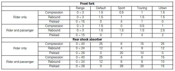
When carrying a passenger and luggage, set the rear shock absorber spring to proper preload to improve motorcycle handling and keep safe clearance from the ground. It may also be necessary to adjust the rebound damping accordingly.
Values specified in the table are indicative and refer to a rider
Weighing (with clothes on) 80-90kg and a passenger
Weighing (with clothes on) 70-80kg.
 Adjusting the front fork
The front fork used on this motorcycle has rebound,
compression and spring preload adjustment.
The settings are adjusted using external adjuster screws.
To adjust rebound damping (fig. 109);
...

Other materials:
Exhaust system
Screw
Bush
Vibration damper mount
Silencer
Washer
Screw
Bracket
Nut
Nut
Upper heat guard
Screw
Washer
Central heat guard
Spacer
Clip nut
Long exhaust spring
Plug
Sealing washer, thickness 1
Vertical exhaust pipe
Lambda sensor
Nut
Vertical flange
Exh ...
Adjusting the rear shock absorber
The adjuster (1) located on the lower connection holding the shock absorber
to the swingarm adjusts the damping during
the rebound phase (return).
The knob (2), located on the left side of the motorcycle, adjusts the preload of
the shock absorber external spring.
Turn the adjuster (1) clock ...
Warning indication (alarms/signals)
The dashboard activates in real-time some warnings / malfunction that are not
dangerous for the correct operation of the
vehicle.
At key-on (at the end of the check) one or more "warnings" are displayed if they
are active.
When a "warning" is triggered, the indication (amber yellow) remai ...