
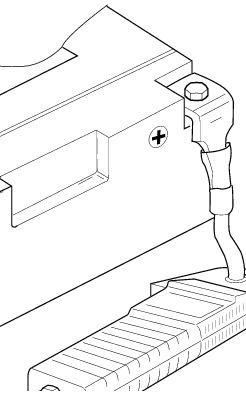
Ducati Diavel Service Manual: Checking the battery charging system
To check the current flow of the recharging circuit, use the "dds" diagnosis instrument, which is equipped with an inductive clamp-type amperemeter: refer to chapter "testing the battery charging system", sect. 6 - 11 With the dds diagnosis instrument you can determine the engine rpm required for the alternator to produce sufficient current to charge the battery, feed the injection/ignition system and all the electrical equipment on the motorcycle. When applied to a cable, the clamp-type amperemeter detects the magnetic field generated by the current passing through that cable.
The tester performs an automatic calibration routine using its own transducer. If the measured current is a positive quantity, it means that generator is feeding all electric items and charging battery at the same time. A negative value means that charging system is not powering the loads and a significant amount of current must be supplied by the battery, which is discharging at the time of the measurement.
Or it is possible to use a multimeter (sect. 6 -11, Diagnostic instruments); connect the multimeter probes to the battery terminals, select the dc scale on the instrument and check for the presence of 14.5 V+/-0.5 At an engine speed of 3000 rpm.
Important
If polarity is reversed when clamping the ammeter onto the cable, the sign of the readings will also be reversed, giving rise to incorrect diagnosis.

 Recharging the battery
Examine the label on the battery showing the check intervals in order to
determine when to test the voltage.
Charge the battery if the open circuit voltage is lower than 12.8 V. Leaving
the b ...
Other materials:
Traction control (dtc) deactivated
The activation of this (amber yellow) "warning" indicates
that dtc (ducati traction control) has been turned off.
Note
In this case, ducati recommends being very careful
when riding as the vehicle behaviour will be different in
comparison to when operating with the traction control
...
Front brake control
Front brake master cylinder
Brake lever
Special screw
Sealing washer
Screw
Phonic wheel
Brake disc
Pin
Left brake calliper
Boot
Bleed valve
Spare stand
Control unit - front callipers pipe
Microswitch
Oil duct union
Screw
Hose clip
Right brake calliper
Speci ...
Removal of the intake manifold and coolant union
Loosen the clips (f) and remove the hoses (t).
Remove the manifolds (25) undoing the screws (21).
Loosen the clamp (a) and remove the hose (b). Remove the union (12) and
recover the seal (24).
...