
Ducati Diavel Service Manual: Overhauling the front wheel
Wheel bearings
Before checking the dimensions, check the wear on wheel bearings. Check for wear by hand after cleaning and degreasing the bearings in their seats.
Turn the inner race.
Check the amount of radial and axial play. Excessive play will cause vibration and make the bike unstable.
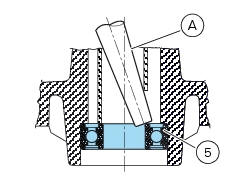
To remove the bearings (5) and the sealing rings (4) from the wheel hub follow the instructions below.
Position a drift (a) against the inner race of the bearing (5).
Tap with a hammer until knocking out the bearing (5).
Apply the drift at different points to keep the bearing square during removal.
Important
Once removed, the used bearings and sealing rings must not be refitted.
Before fitting new bearings, check that the housing is clean and free from scoring and damage.
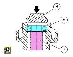
Grease the bearing seat and then push the new bearing into its seat.
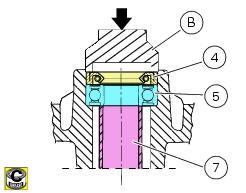
Using a tubular drift (b) that only bears on the outer race of the bearing, drive the bearing (5) fully into its seat.
Use the same method to install the sealing rings (4).
Ensure that spacer (7) is fitted between the two wheel bearings.
Note
Wheels must be rebalanced after repair, maintenance and overhaul operations.
Inspecting the wheel axle
Check the wheel shaft for straightness.
Turn the pin on a reference surface and measure maximum distortion using a feeler gauge (see sect. 3 - 1.1, Front wheel).
Overhauling the wheel
After you have checked the bearings, check the rim as follows.
Visually inspect the wheel for cracks, scoring and deformation; change the wheel if damaged.
Insert the shaft in the wheel and mount it on two fixed reference blocks.
Using a dial gauge, measure rim run-out and out-of-round relative to the pin axle (see sect. 3 - 1.1, Front wheel).
If the values measured are not within the tolerance limits, renew the wheel.
 Removal of the front wheel
Support the bike so that the front wheel is raised from the ground.
Remove the front brake calliper (b) by unscrewing the two screws (a) securing
the calliper to the fork leg; do not
disconnect ...
 Refitting the front wheel
When all the necessary inspections have been completed, refit the wheel as
follows.
Fit the spacers (3) and (9) to the seal rings on the sides of the wheel hub.
Install the complete whee ...
Other materials:
Refitting the rear wheel eccentric hub and rear wheel shaft
Refitting is the reverse of removal, with attention to the following points.
If the calliper bracket locating pin (14) was removed, apply the recommended
threadlocker on reassembly.
Tighten the pin (14) to the torque of 33 nm +/- 5% (sect. 3 - 3, Frame torque
settings).
If previously ...
Engine speed-timing sensor
Introduction
The engine control system of the diavel is equipped with an inductive sensor
that allows the ecu to determine the speed
and timing phase of the engine. The sensor faces a phonic wheel with 48 teeth
minus 2.
The engine speed-timing sensor is an inductive sensor and faces a 48 ...
Operating principle and characteristics of the ride-by-wire system
The engine control system of the diavel uses a ride-by-wire system with
motorised throttle valves. This eliminates all
direct connection with metal cables between the throttle grip and the throttle
valves themselves. Cables are used to
rotate the aps potentiometer, which generates an electric ...