
Ducati Diavel Service Manual: Checking the fuses
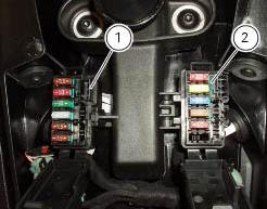
The main fuse box (1) and the secondary one (2) are located in the tool tray; to reach the fuse box remove the seat as specified under sect. 5 - 3 "Removal of the seat".
The fuses are accessed by removing the cover, which shows the ampere ratings and mounting locations.
For ampere ratings, refer to the chapter "routing of wiring on frame", sect. 6 - 1.
Important
Before replacing a damaged fuse with a new one of the same rating, identify the cause of the problem.
A blown fuse can be identified by the breakage of inner filament (a).
Important
Switch the ignition key to off before replacing a fuse to avoid possible short circuits.
Warning
Never use a fuse with a rating other than the specified value. Failure to observe this rule may damage the electric system or even cause fire.
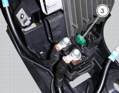
Besides the fuses inside the box, the motorcycle is also provided with one 30 a fuse (3), located near the voltage regulator (in the electrical components compartment) that protects the electronic rectifier (sect. 6 - 2, Rectifierregulator).
 Checking protection and safety device components
Checking the side stand switch
Remove the switch (1) from the side stand undoing screw (2) and disconnect
the main wiring connector from the switch
(see paragraph "routing of wiring on frame", sec ...
 Instruments
...
Other materials:
Checking and overhauling the components
Clearance between the clutch drum and friction plates
Insert a friction plate (e) in the clutch drum (f) and measure the clearance
(s) with a feeler gauge.
Clearance "s" must not exceed 0.6 Mm.
If it does, renew the plates and, if necessary, the clutch drum.
Overhaul of the clutch plat ...
Indicator air - air temperature
This function shows the external temperature.
Display limits: -39C - +124C
In the event of a sensor fault (-40C, +125C or disconnected), a string of
dashes "- - -" (not flashing) is displayed and
the "vehicle/engine diagnosis - eobd" light comes on.
Note
When the vehicle is stopped, the ...
Distance travelled on fuel reserve: trip fuel
This function shows the distance travelled on fuel reserve (in km or miles
depending on the specific application).
When the fuel light comes on, the display automatically switches to the "trip
fuel" indicator.
Trip fuel reading remains stored even after key-off until the vehicle is
refue ...