
Ducati Diavel Service Manual: Checking protection and safety device components
Checking the side stand switch
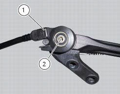
Remove the switch (1) from the side stand undoing screw (2) and disconnect the main wiring connector from the switch (see paragraph "routing of wiring on frame", sect. 6 - 1).
Use an analogue or digital multimeter (sect. 6 - 11, Using a multimeter to check the electrical systems) to check switch operation (see table).
Note
The same test may be carried out using the "dds" tester (sect. 6 - 11,
Diagnostic instruments). 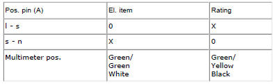
0 = Open contact
X = closed contact
Refit switch (1) to side stand and tighten the screw (2) to a torque of 5 nm +/-10 (sect. 3 - 3, Frame torque settings).

 Checking the fuses
The main fuse box (1) and the secondary one (2) are located in the tool tray;
to reach the fuse box remove the seat as
specified under sect. 5 - 3 "Removal of the seat".
The fuses are accessed b ...
Other materials:
Footrest brackets
Rubber footrest
Right front footrest
Pin
Spring
Circlip
Right footrest bracket
Screw
Washer
O-ring
Bush
Rubber pad
Right rear footrest
Pin
Ball
Spring
Plate
Screw
Vibration damper mount
Special screw
Front lh footrest
Left footrest bracket
Left rear f ...
General cleaning
To preserve the finish of metal parts and paintwork, wash
and clean your motorcycle at regular intervals, anyway
according to the road conditions you ride in. Use specific
products, where possible biodegradable. Avoid aggressive
detergents or solvents.
Use only water and neutral soap to clean ...
Reassembly of structural components and the frame
Check for the nuts with clips (8).
Apply recommended grease on the threads of the adjusters (4) and the ring
nuts (5) having care not to have grease on
the surface (c) of the adjusters.
Tighten the adjusters on the ring nut side opposite to that featuring flats
until bringing the surfac ...