
Ducati Diavel Service Manual: Deactivating the service indication on the dashboard
The message "serv" is displayed on the dashboard, indicating that the motorcycle should be serviced in accordance with the programmed maintenance plan. This indication is activated after the first 1000 km and thereafter at intervals of 12000 km.
After the scheduled service has been carried out, the indication must be switched off as follows:
Note
The on-screen icons used during this procedure are explained in a table at the end of this section.
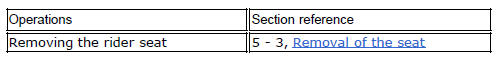
Turn on the dds diagnosis instrument (1) referring to the paragraph "tester power supply".
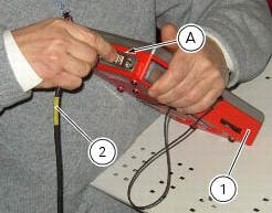
Connect the power and diagnosis cable (2) part no. 97900.0222 To the diagnosis connector (a) and the latter to the diagnosis socket (3) of the motorcycle.
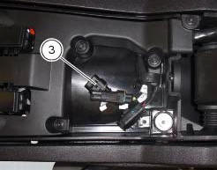
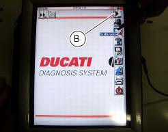
Enter the general functions menu, pressing "menu key 1" icon (b).
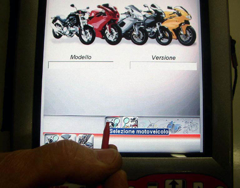
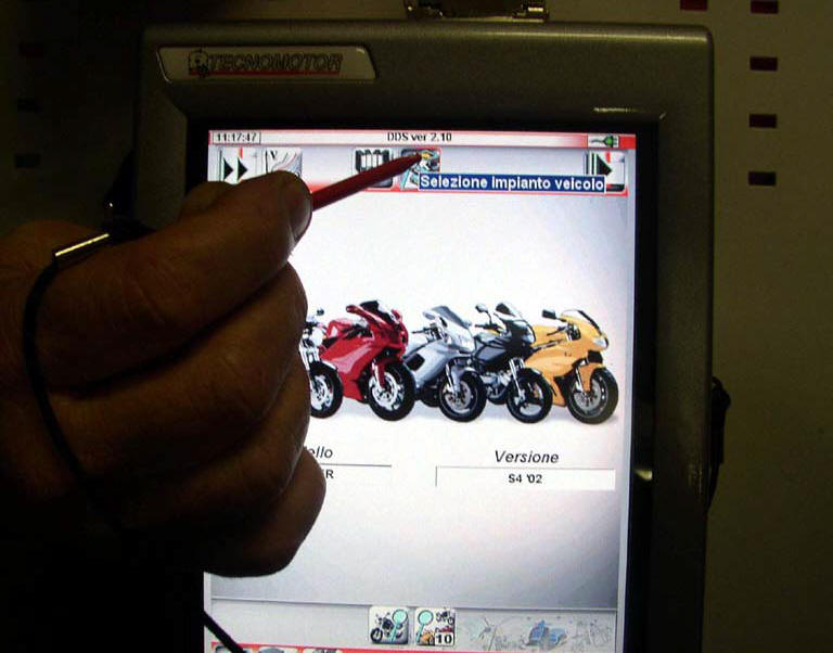
Press the "vehicle selection" icon and press "vehicle selection" icon in the following page; select the motorcycle model and confirm, then select the version and confirm.Press the "select system" icon.
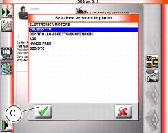
A list of the motorcycle’s systems that can be analysed will appear on the display.
Select the icon "dashboard".
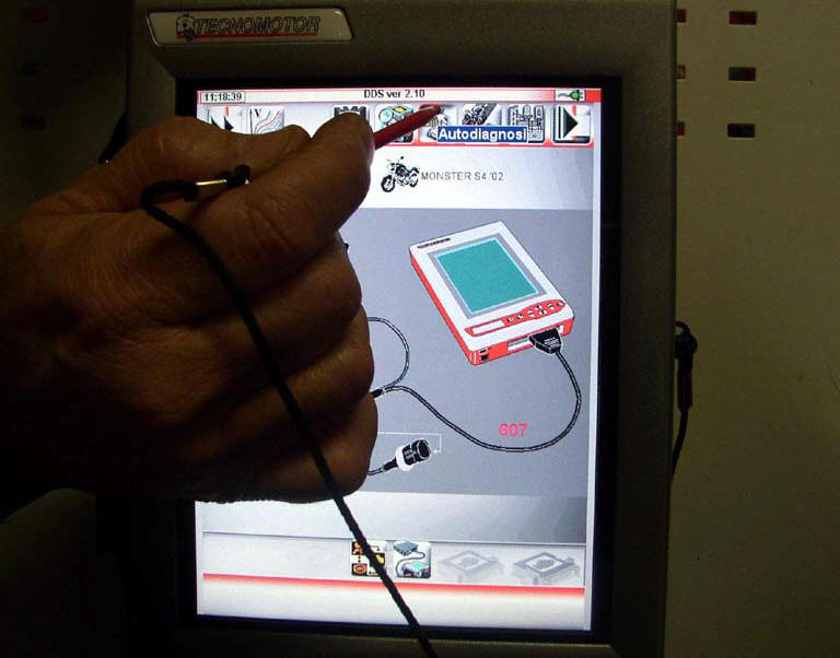
Press the "confirm" icon (c). Next, press the "self-diagnosis" icon to access the corresponding function.
The dds diagnosis instrument will interrogate the electronic control unit and display the parameters analysed with their relative values.
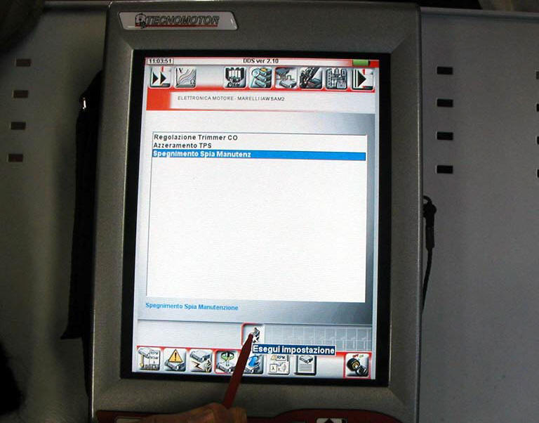
Press the "settings" icon to display the special parameters.
Select "service light off" and press "execute".
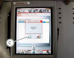
On completion of the operation, the message "was the operation completed successfully?" Will appear; press "confirm" (c).
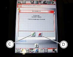
If any problems were encountered during the operation, the tester will display the relative error messages: you need to confirm or reject each message by pressing "confirm" (c) or "exit" (d), respectively.
Note
Once the "service" light has been reset with the dds diagnosis instrument, set the ignition switch to off and wait for at least 30 seconds before switching it on again.
 Testing the battery charging system
Note
The on-screen icons used during this procedure are explained in a table at
the end of this section.
You can determine the engine rpm required for generator to produce just
enough current to ...
 Abs diagnosis
Note
The on-screen icons used during this procedure are explained in a table at
the end of this section.
If the abs system is not working correctly, system diagnosis is possible
through the dds ...
Other materials:
Tubeless tyres
Front tyre pressure:
2.50 Bar (rider only) - 2.6 Bar (with passenger and/or bags)
rear tyre pressure:
2.50 Bar (rider only) - 2.6 Bar (with passenger and/or bags)
as tyre pressures are affected by changes in temperature
and altitude; check and adjust them whenever you are riding
in areas where ...
Scheduled maintenance chart
Operations to be carried out by the dealer
List of operations to be performed at 1000 km
Reading of the error memory with dds on the engine control units, vehicle and
abs
Change the engine oil
Change the engine oil filter
Check the indicators and lighting
Check the safety devices (side stand ...
Reassembly of rear shock absorber - rocker arm - linkage assembly
Once the needle roller bearings (9) have been removed from the rocker arm
(18), upon reassembly fit a new needle roller
bearing (9) on drift part no. 88713.1071 And lubricate with recommended grease.
Support the rocker arm and drive the needle roller bearings into the rocker arm
bore until t ...