
Ducati Diavel Service Manual: Clock setting function
This function sets the clock.
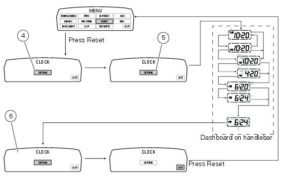
To access the function it is necessary to view the ""setting" menu", using buttons (1) "s" or (2) "t" select the "clock" function and press the reset button (3) to confirm.
In the following screen the message "setting" is highlighted in green (4); now, press the reset button (3) for 3 seconds to edit the time displayed on the handlebar dashboard, and the "setting" indication highlighting becomes grey (5).
Clock setting
On entering this mode, the message "am" will flash; press button (2) "t", the message "pm" starts flashing; press button (2) "t" to return to the previous step (if the current time is 00:00, 12:00 will be displayed when switching from "am" to "pm"); press button (1) "s" to access the hour setting mode; the hour value starts to flash; each time button (2) "t" is pressed increases the digit by 1 hour; pressing and holding button (2) "t", the digit increases by 1 hour every second (the hour value does not flash while the button is kept pressed).
Pressing button (1) "s" gives access to the minute setting mode; minutes start to flash.
Each time button (2) "t" is pressed increases the digit by 1 minute; pressing and holding button (2) "t", the digit increases by 1 minute each second; pressing and holding the button (2) "t" for more than 5 seconds, the value increases by 1 every 100 m (the second value does not flash while button (2) "t" is kept pressed).
If you press button (1) "s" setting is completed and the tank dashboard display "setting" item is again highlighted in green (6).
To exit, select "exit" and press the reset button (3).
Note
In case of a battery is cutoff, when the voltage is restored and at the next key-on, the clock is always reset (it starts automatically from 00:00).
 Battery voltage indicator (battery)
This function describes the battery voltage indicator.
To access the function it is necessary to view the ""setting" menu", using
buttons (1) "s" or (2) "t" select the "battery"
function and pre ...
 Units of measurement modification function
This function allows you to change the units of measurement of the displayed
values.
To access the function it is necessary to view the ""setting" menu", using
buttons (1) "s" or (2) "t" to sel ...
Other materials:
Refitting the abs control unit
If the brake hoses (7), (8), (9) and (10) on the abs control unit are changed
or removed, ensure that the fittings on the
control unit are positioned correctly.
Warning
If incorrectly positioned, the hose can affect brake operation and
foul moving parts. Position the hose as shown in the
fig ...
Throttle twistgrip
Upper clamp
Counterweight
Screw
Handlebar
Grips
Throttle twistgrip
Bush
Screw
Bush
Throttle cables
Spare parts catalogue
Diavel abs handlebar and controls
Diavel carbon
abs
handlebar and controls
Important
Bold reference numbers in this section identify parts not sh ...
Refitting the intake manifold and coolant union
Apply prescribed threadlocker to the fitting (12), start it with seal (24)
and tighten it to a torque of 2.5 Nm (min. 2 Nm -
max. 3 Nm) (sect. 3 - 3, Frame torque settings).
Install the pipe (b) and tighten the clamp (a) to the torque of 1 nm +/- 10%
(sect. 3 - 3, Engine torque settings).
...