
Ducati Diavel Service Manual: Engine start button
Introduction
The engine start button is located on the right hand handlebar switchgear set and is used to turn the engine on.
Component assembling position
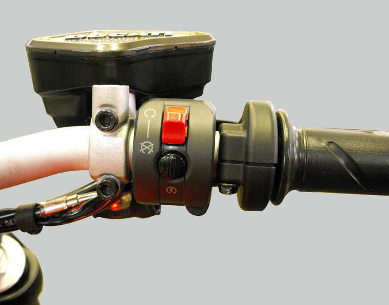
The engine start button is included in the switchgear set on the right hand handlebar.
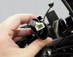
Location of right hand handlebar switchgear set connection.
Connection wiring diagram
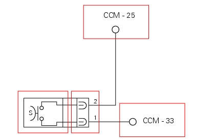
Ccm engine control connection, s engine start button. 1 Pink/black - p/bk, 2 white/blue - w/b.
In the event of fault
In the event of a start button fault, the engine cannot be started.
Fault codes generated and possible correlated faults
The engine control unit generates no fault code in the event of an engine start button fault.
No errors are indicated on the dashboard
Possible correlated faults: the starter motor cannot be operated. Check:
- Battery charge.
- Integrity of the electric circuit (open circuit, short circuit to ground and toward vdc) and electrical connections of the start button.
- Integrity of the start button. In the button's two different positions, the resistance at its contacts (pin 1 and pin 2) must be zero (depressed - continuity) or infinite (released - open circuit).
- The integrity of the engine starter motor relay and its circuit.
- Integrity of the starter motor and that the motor is correctly connected to the electrical system (also check ground connection on engine, see sect. 6 - 3"Starter motor").
- The integrity of the side stand switch, the clutch lever switch, the gear position sensor and their respective circuits
- Integrity of stop engine switch.
Note
Check integrity of electric circuit - short-circuit to vdc = with dashboard on, using a voltmeter, a voltage is measured between the wire tested and ground.
Check integrity of electric circuit - short-circuit to ground = with the battery cables disconnected, using an ohmmeter, continuity is detected between the wire tested and ground.
Check integrity of electric circuit - open circuit = with the battery cables disconnected, using an ohmmeter, no continuity is detected between the two ends of the wire tested.
The dds instrument can be used to display the activation state of the engine start button.
If none of the tests described above identifies the problem and the power supply and ground for the engine control unit are in correct working order, replace the engine control unit.
Component replacement methods
No special measures are necessary in order to replace the starter button.
Checking the right-hand handlebar switch
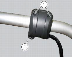
To remove the right-hand handlebar switch, undo the retaining screws (1) and disconnect the wiring connector from the electric system.
Refitting is the reverse of removal; tighten the screws (1) to a torque of 1.3 Nm +/- 10% (sect. 3 - 3, Frame torque settings).
 Throttle valve operation engine
Introduction
The electric motor actuating the throttle valve for the vertical cylinder is
mounted on the throttle body of the diavel, while
a link rod connects the vertical cylinder throttle valve ...
 Clutch lever button
Introduction
The clutch button is located on the clutch lever. Together with the signal
from the side stand button and the neutral signal
generated by the gear sensor (transmitted to the engine co ...
Other materials:
Gearchange mechanism
Gearchange pedal
Bush
Rubber pad
Pin
O-ring
Gearchange lever tie-rod
Screw
Gearchange lever
Washer
Screw
Ball joint
Nut
Nut
Nut with left-hand thread
Lh ball joint
Spare parts catalogue
Diavel abs l.H. Footrests
Diavel carbon
abs
l.H. Footrests
Important
B ...
Number plate light not working
Fault codes
Dds: no fault code displayed.
Dashboard: no fault code displayed.
Location of connections and components
Location of rear turn indicator and number plate light connection.
pin numbering for wiring harness side dashboard connector.
Checks
The number plate light receives p ...
Refitting the external components
Fit the cap (39) on spring (38) until it engages.
Mount ball (40), spring (38) with cap (39), washer (37) and screw (36) on the
chain side half-casing by starting the
screw into hole (f).
Note
The spring (38), with cap (39), must be oriented as shown.
Tighten the screw fully home to a torqu ...