
Ducati Diavel Service Manual: Clutch lever button
Introduction
The clutch button is located on the clutch lever. Together with the signal from the side stand button and the neutral signal generated by the gear sensor (transmitted to the engine control unit over the can line), the clutch lever position signal is used to enable or disable engine start.
The following table indicates the only conditions in which starter motor
activation and, as a result, engine start, are
permitted: 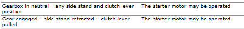
If a gear is engaged with the side stand down, however, the engine switches off.
The engine control unit recognises the idle speed state when engine speed drops below a certain threshold and when the ecu itself receives the clutch lever pulled and/or gearbox in neutral signal (generated by gear sensor).
Component assembling position
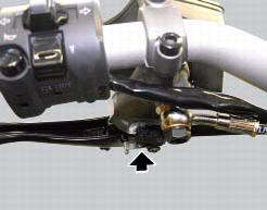
The clutch button is located under the lever.
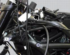
Location of clutch button connection.
Connection wiring diagram
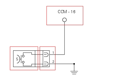
Ccm engine control connection, s clutch button. 2 Ground, black - bk, 1 white - w.
In the event of fault
In the event of a clutch button fault, the operating conditions described in the introduction are not met.
Fault codes generated and possible correlated faults
The engine control unit generates no fault code in the event of a clutch button fault.
No errors are indicated on the dashboard.
Possible correlated faults: the safety conditions required to enable engine start are not met, incorrect idle speed (target idle speed is 1350 rpm with engine stabilised at operating temperature). Check:
- Integrity of electric circuit (open circuit, short-circuit to ground and toward vdc) and of the electrical connections.
- Integrity of the clutch button. When the clutch lever is operated (pulled and released), the resistance on the button contacts (pin 1 and pin 2) must be zero in one position (continuity) and infinite in the other (open circuit).
Note
Check integrity of electric circuit - short-circuit to vdc = with dashboard on, using a voltmeter, a voltage is measured between the wire tested and ground
Check integrity of electric circuit - short-circuit to ground = with the battery cables disconnected, using an ohmmeter, continuity is detected between the wire tested and ground
Check integrity of electric circuit - open circuit = with the battery cables disconnected, using an ohmmeter, no continuity is detected between the two ends of the wire tested.
The dds instrument can be used to display the activation state of the clutch button.
If none of the aforementioned tests identify the problem and the clutch button is in proper working order, replace the engine control unit.
Component replacement methods
No special measures are necessary in order to replace the clutch button.
 Engine start button
Introduction
The engine start button is located on the right hand handlebar switchgear set
and is used to turn the engine on.
Component assembling position
The engine start button is included ...
 Side stand button
Introduction
The side stand button is located on the side stand. Together with the signal
from the clutch button and the neutral signal
generated by the gear sensor (transmitted to the engine cont ...
Other materials:
Removal the airbox and throttle body
Loosen the screws (a) and remove the plate (b) that fixes the main wiring to
the airbox.
Undo the screws (17) and remove the air pressure sensors (9) with the support
(19).
Release the hoses (c) of the air pressure sensors (9) from the tab (d) on the
airbox.
Operating on the ...
Checking drive chain tension
Important
Have chain tension adjusted by a ducati dealer or
authorised service centre.
Make the rear wheel turn until you find the position where
chain is tightest.
Set the vehicle on the side stand. Push down the chain at the
point of measurement and release.
Measure the distance betwee ...
Removal of the rear brake disc
Remove the rear eccentric hub (sec. 7 - 13, Removal of the rear wheel
eccentric hub and rear wheel shaft).
Undo and remove the four fixing screws (13) of the brake disk to the wheel axle
and remove the rear brake disk (14).
Loosen the four screws (24) and remove the rear phonic wheel (25). ...