
Ducati Diavel Service Manual: Fuel pressure test
Note
The on-screen icons used during this procedure are explained in a table at the end of this section.
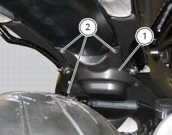
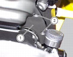
Undo the screws (2) and remove the flange cover (1).

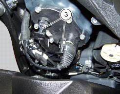
Remove one of the two pipes of the fuel system (3).
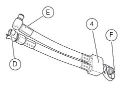
Use the fuel pressure pipe (4) part no. 590.1.189.1A by connecting one end (d) to the coupling of the delivery pipe to the tank and the other end (e) to the fuel system pipe (3): in this way you create a pressure pick-up socket (f).
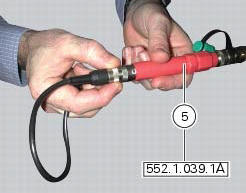
Connect the pressure sensor (5) part no. 552.1.039.1A to the outlet (f) of hose (4), in order to convert the pressure reading into an electric signal.
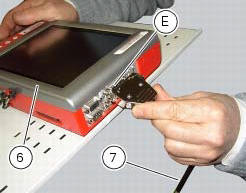
Turn on the dds diagnosis instrument (6) referring to the paragraph "tester power supply".
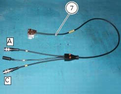
Connect the power and diagnosis cable (measurement module) (7) part no. 97900.0222 To the measurement module connector (e) of the dds (1).
Connect the pressure sensor (6) part no. 552.1.039.1A to outlet (a) or (c) of the cable (7).
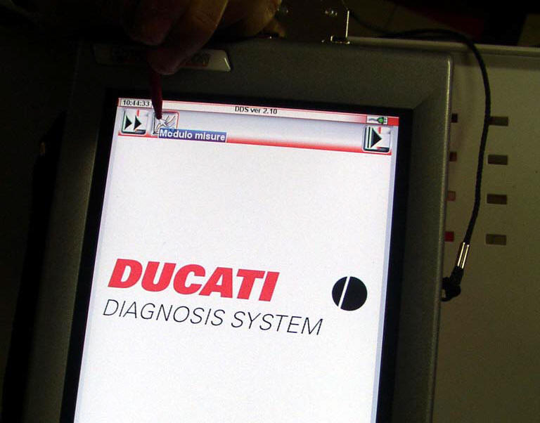
On the dds diagnosis instrument (6), select the "measurement module" function by pressing the corresponding icon; then press the "pressure test" icon (f) followed by the "start" icon (g).
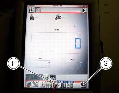
The socket to which the cable (measurement module) (7) is to be connected is indicated on the screen with a capital letter: a, b or c.
The values may be displayed in three different ways: in one numeric form and in two graphic forms; to select the desired display type, press the "value display" icon (h).
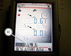
The measured value is indicated alongside the letter (a) or (c) identifying the cable used for the measurement: i.E. If you used socket (a) of the cable (7), the value measured will be displayed next to the letter (a) on the screen.
The maximum pressure must be equal 3 bar (nominal).
Once the test is over, remove all the components of the test instrument and refit the fuel system pipe (3).

Refit the flange cover (1) by tightening the screws (2) to a torque of 4 nm +/- 10% (sect. 3 - 3, Frame torque settings).

 Cylinder compression test
Note
The on-screen icons used during this procedure are explained in a table at
the end of this section.
Engine performance is directly correlated to the pressure that can be
measured in the com ...
 Guided diagnosis
Note
The on-screen icons used during this procedure are explained in a table at
the end of this section.
The dds diagnosis instrument guides the operator step-by-step through the
various diagnos ...
Other materials:
Steering head: front fork
Screw
Screw
Steering head
Bottom yoke
Left fork leg assembly
Right fork leg assembly
Counter nut
Damper assembly
Bush
Spring
Preload tube
Collar
Washer
Top cap assembly
Screw
Washer
Adjuster screw
Special washer
Fork tube + calliper unit
Dust cap
Sealin ...
Checking brake pad wear and changing brake pads
Warning
Brake fluid is corrosive and will damage paintwork. Avoid contact
with eyes and skin. In the case of accidental contact,
wash the affected area thoroughly with plenty of running water.
Important
On handing over the motorcycle after changing the brake pads, inform the
customer that th ...
Operating principle
The ducati abs brake system manages the front and rear brakes separately. A
pulse generator (phonic wheel), with a
ring of slots, is fixed onto each wheel. On the left calliper mounting bracket
of the front fork and on the rear brake calliper
holder plate are hall effect sensors which detect t ...