
Ducati Diavel Service Manual: Routing of wiring on frame
The routing of the wiring has been optimised to ensure the minimum obstruction.
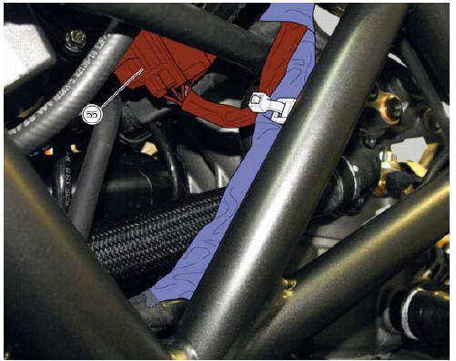
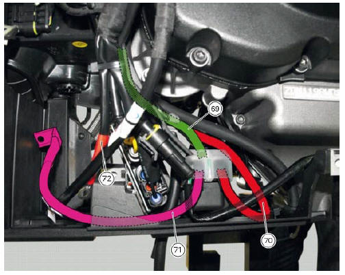
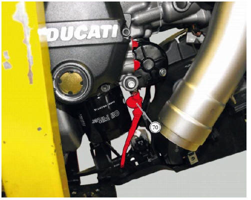
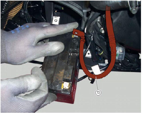
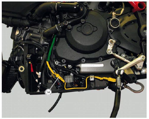
Each section is designed to prevent interference with parts that might damage wires or cause operating failures when riding. The plates on the following pages show the origins ("0" points) for correct re-routing of wiring and the locations of cable ties.
Each figure includes references to the plates showing the wiring routing or the item to which it must be connected.
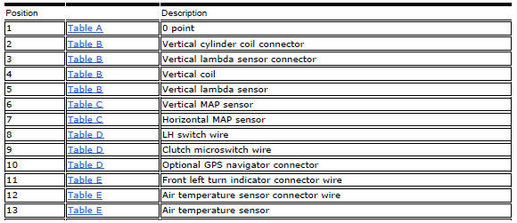
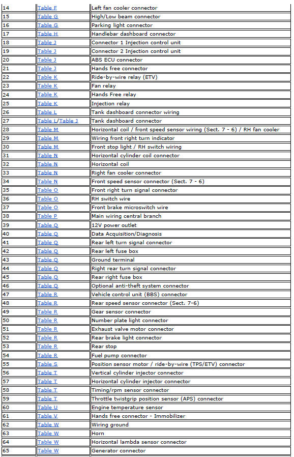
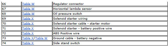
Table a
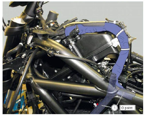
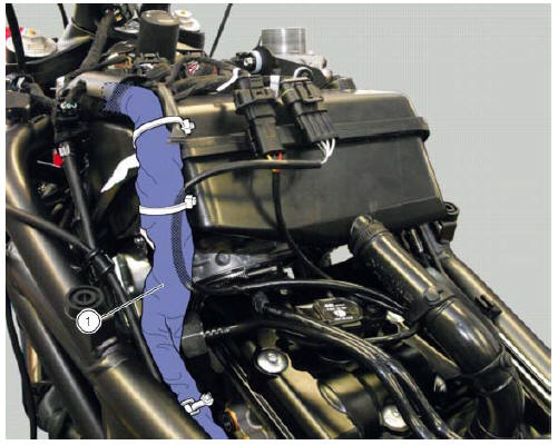
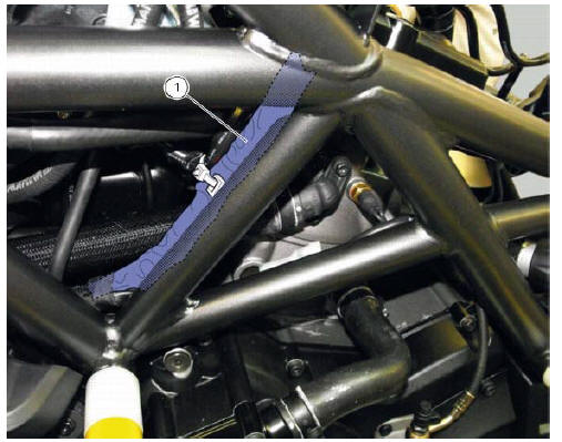
Table b
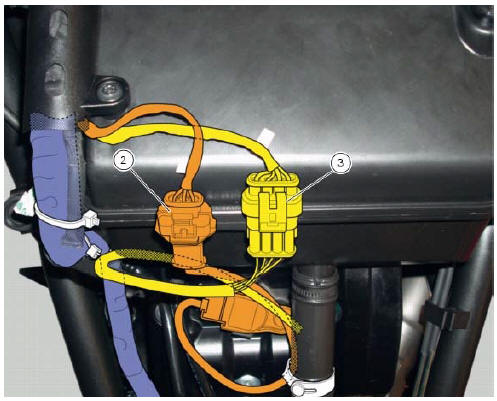
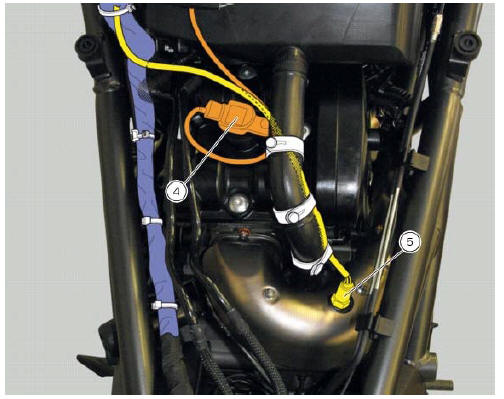
Table c
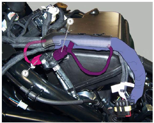
Table d
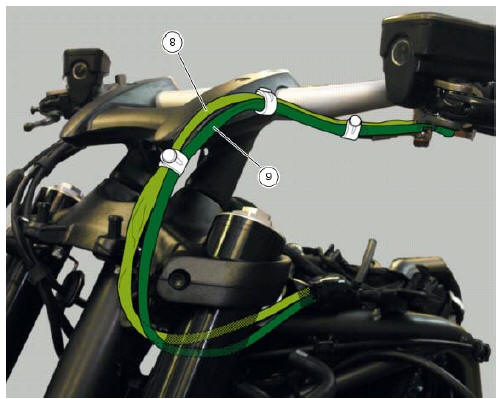
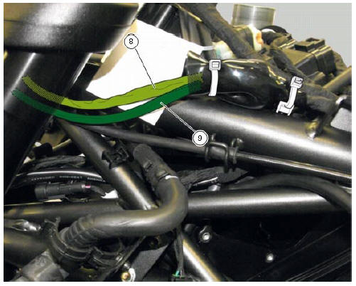
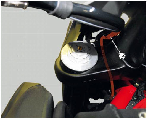
Table e
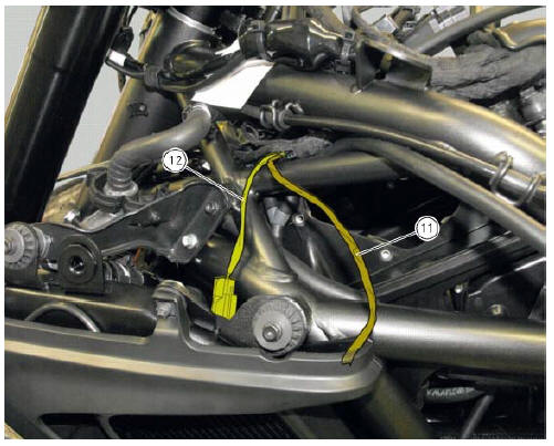
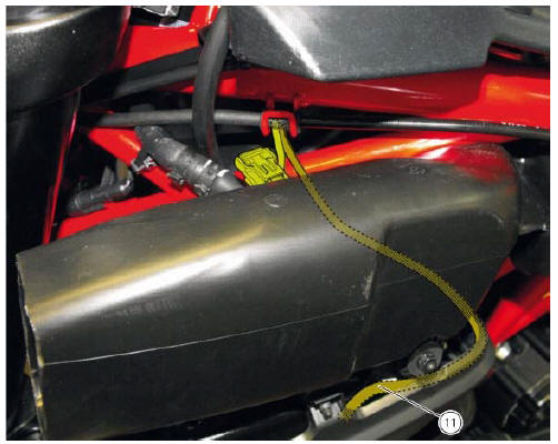
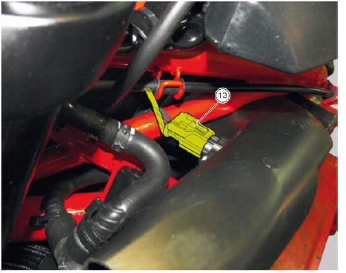
Table f
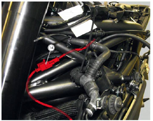
Table g
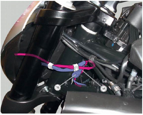
Table h
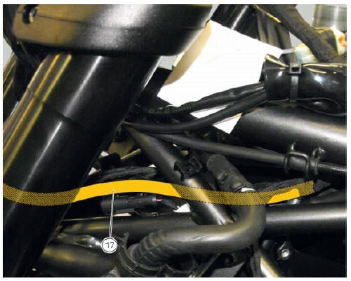
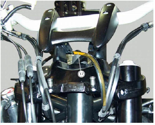
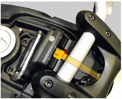
Table j
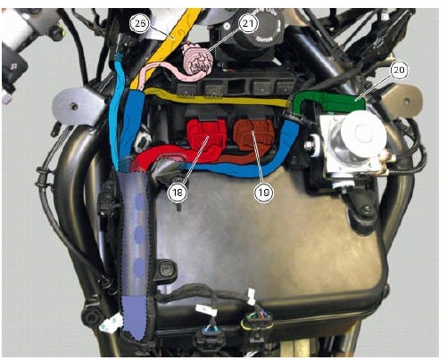
Table k
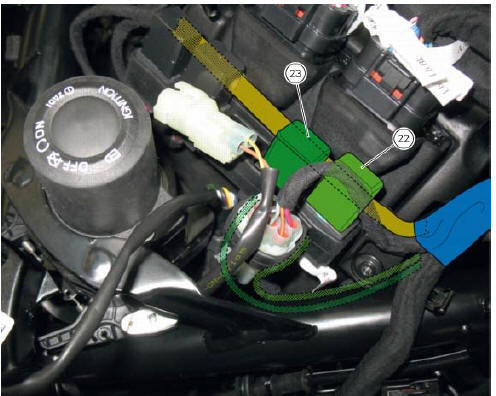
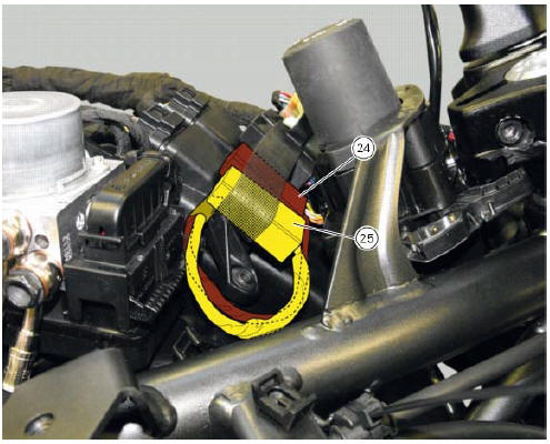
Table l
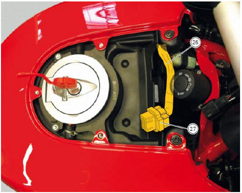
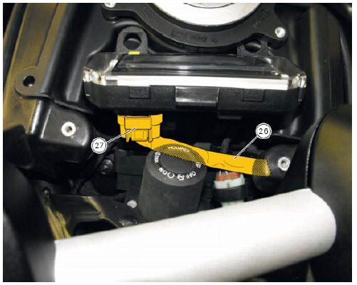
Table m
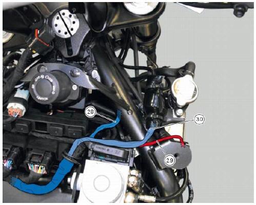
Table n
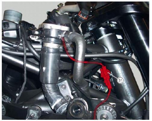
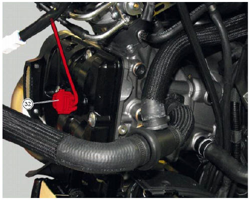
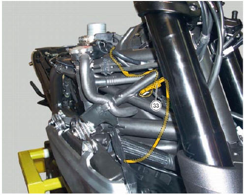
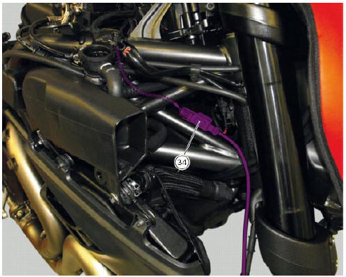
Table o
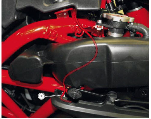
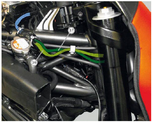
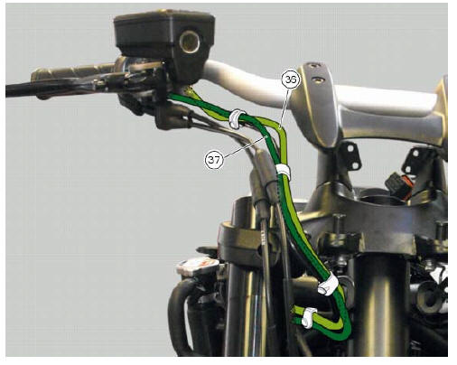
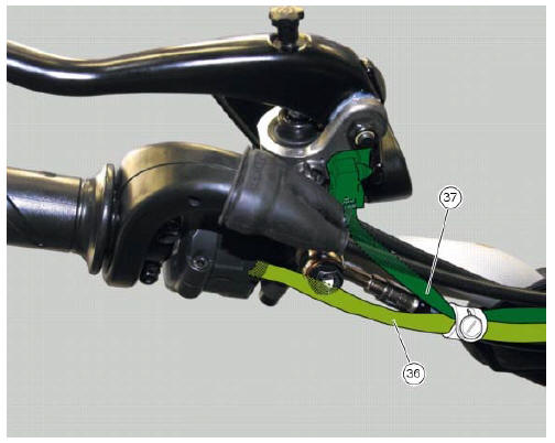
Table p
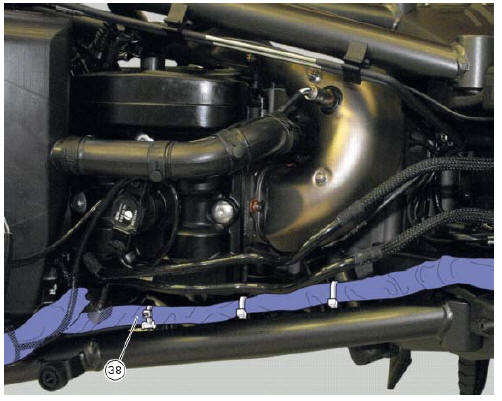
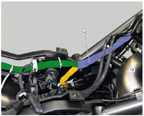
Table q
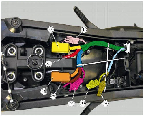
Table r
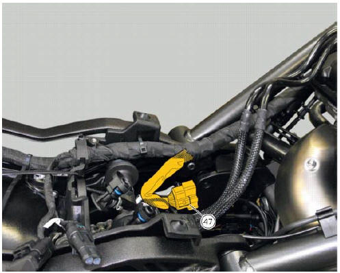
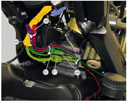
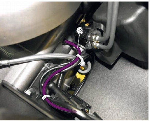
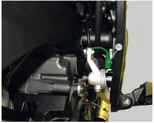
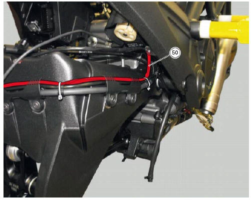
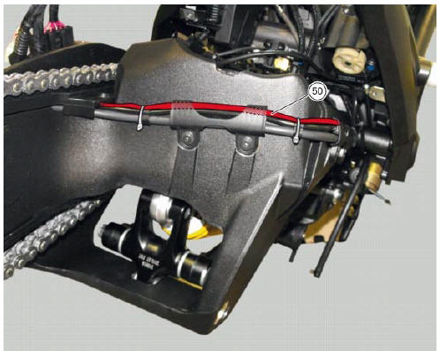
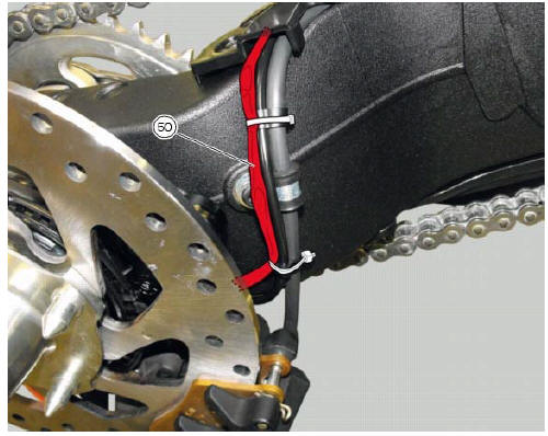
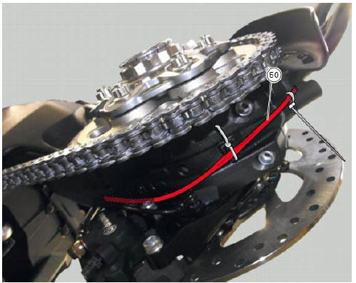
Table s
Table
t
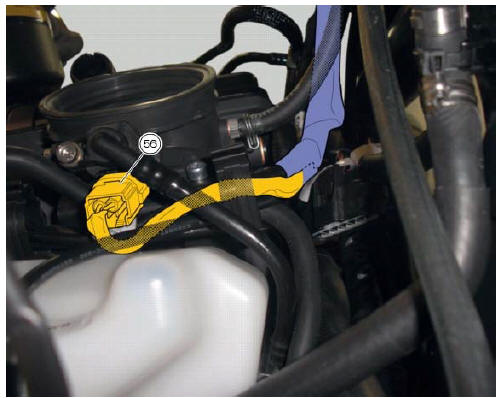
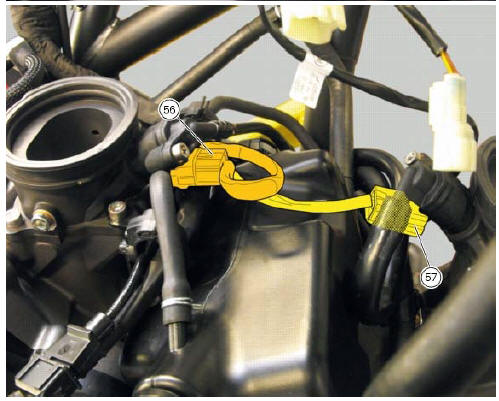
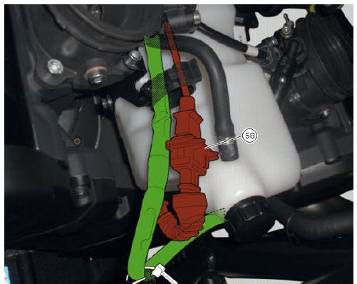
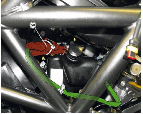
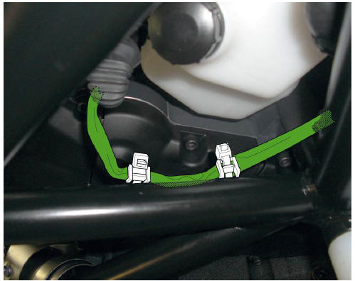
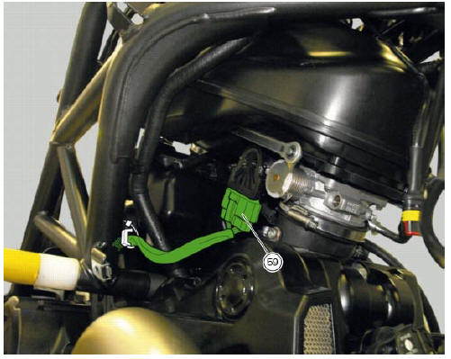
Table u
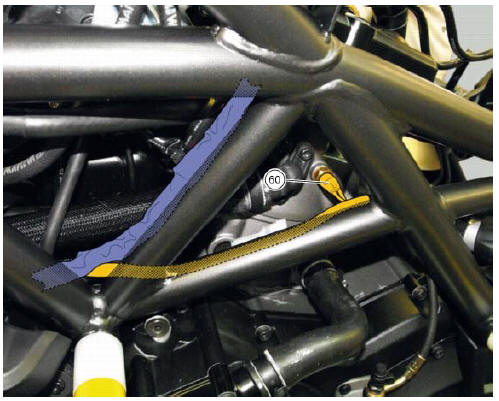
Table v

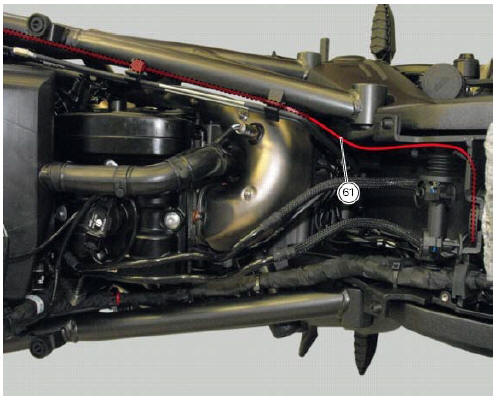
Table w
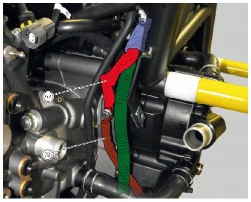
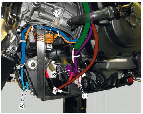
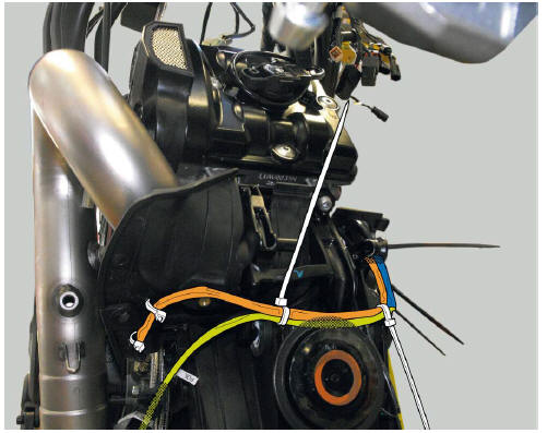
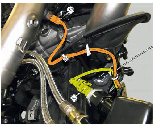
Table x

 Wiring diagram colour codes
B blue
Bk black
Bn brown
G green
Gr grey
Lb light blue
O orange
P pink
R red
V violet
W white
Y yellow
Rear left fuse box (1) key
Rear right fuse box (2) key
...

Other materials:
Replacing the rear phonic wheel sensor
Disconnect the rear abs sensor (5) connector (c) from the main electric
wiring.
Open all the retainer clamps of the rear abs sensor cable (5): refer to table of
sect. 7 - 6, Flexible wiring/hoses
positioning.
Remove the rear abs sensor (5) from its seat on the rear calliper mounting ...
Reassembly of the gearbox
To refit the gearbox components follow the procedure under sect. 9 - 9.2,
Reassembly of the crankcase halves, relating to
reassembly of the engine crankcase.
As a final practical test, ensure that with the gearbox in neutral the front
coupling dogs (a) of sliding gears (b) are
equidistant o ...
How to reset the pin code
The pin code can be reset with the dds, i.E. It can be brought to the same
condition it was in when the bike came out
the factory. It is possible to complete the procedure with the relevant pin code
reset function.
Once the pin code has been reset it will be necessary to store a new one. In ...