
Ducati Diavel Service Manual: Gear indicator display on dashboard shows dashes, engaged gear not displayed correctly, idle speed irregular with gearbox in neutral
Fault codes
Dds: gear sensor diagnosis -> short circuit to ground or open circuit (s.C. Gnd or c.O.) - Short circuit to vdc (s.C. Vdc) - congruence (generic error - signal not correct).
Dashboard: the error "gear sensor" is shown on the service display. The eobd warning light activates.
Fault indication
If the dashboard receives the "gear" error information via the can line:
- The error is indicated on the dashboard service display.
- The dashboard shows dashes in the gear indicator display instead of the gear engaged.
If the dashboard does not receive the gear or neutral engaged information via the can line:
- The error "gear sensor" is not indicated on the dashboard service display.
- The dashboard causes the neutral indicator to flash
If the dashboard receives incorrect gear engaged information (flashing dashes) via the can line with the engine running:
- The dashboard shows flashing dashes in the gear indicator display.
Warning
It is possible that the gear engaged or neutral engaged information is not being generated because the gear position self-acquisition procedure has not been performed (gear sensor not initialised).

Wiring diagram
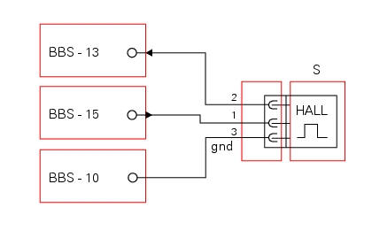
Bbs bbs unit connection, s gear position sensor. Bbs 15 brown/red - br/r (5v), bbs 13 yellow/green y/g, bbs 10 black/blue - bk/b.
Location of connections and components
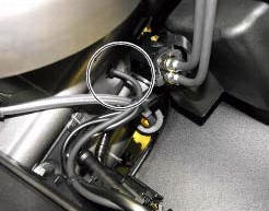
Location of gear sensor connection
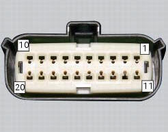
Pin numbering of wiring harness side bbs unit connection.
Checks
The gear sensor is a hall effect unit. Ground is on pin 10 of the bbs unit, 5 v power is on pin 15 of the bbs unit, pin 13 of the bbs is the input for the signal generated by the sensor. Check that the sensor receives 5 v power.
Check the integrity of the electrical circuit and connections (short-circuits to ground, short-circuits to vdc, open circuits).
Perform the gear self-acquisition procedure.
If none of the aforementioned tests identify the problem, replace the gear sensor then perform the gear self-acquisition procedure. If the fault has not been resolved, replace the bbs unit.
Warning
The engine control unit uses the neutral engaged signal generated by the gear sensor, together with the clutch lever pulled signal, to manage idle speed.
Note
Check integrity of electric circuit - short-circuit to vdc = with dashboard on, using a voltmeter, a voltage is measured between the wire tested and ground.
Check integrity of electric circuit - short-circuit to ground = with the battery cables disconnected, using an ohmmeter, continuity is detected between the wire tested and ground.
Check integrity of electric circuit - open circuit = with the battery cables disconnected, using an ohmmeter, no continuity is detected between the two ends of the wire tested.
Gear self-acquisition procedure
The gear self-acquisition procedure must be launched from the dds instrument. This ensures that the data stored previously is deleted and enables the bbs to run a new gear acquisition procedure. With the engine running and the motorcycle in motion:
- Select neutral, pulling the clutch lever completely, dashes "- -" appear in the gear indicator display. Release the clutch, the letter "c" appears in the display. Keep the motorcycle in this gear for at least five seconds. Then, engage first gear.
- Repeat the above procedure through all the gears, up to sixth gear.
- Downshift through the gears from sixth to first, pulling the clutch lever completely before and releasing after each gear change.
- Reselect neutral and keep in neutral for at least five seconds, repeatedly pulling the clutch lever completely and releasing.
- Shift up through the gears from first to sixth, pulling the clutch lever completely.
- Downshift through all gears to neutral and switch off the motorcycle.
- The self-acquisition procedure is complete.
 Resetting turn indicators not possible - accessing dashboard menu not
possible
Resetting turn indicators not possible - accessing dashboard menu not
possible
Fault codes
Dds: no fault code displayed
Dashboard: no fault code displayed
Location of connections and components
Location of left hand handlebar switchgear set connection.
Pin numbering ...
 Dashes shown instead of speed indication or indicated speed is incorrect
Fault codes
Dds: speed sensor diagnosis -> max. Speed (max. Speed error - signal not
correct) - minimum speed (min speed error -
signal not correct) - congruence (correlation speed error - sign ...
Other materials:
Inputs and outputs of engine control unit and connection to can network
The diagram illustrates the inputs and outputs for the engine control unit.
The signals from the brake buttons, the exhaust
by-pass valve command signal and the gear sensor signal are transmitted over the
can line.
1I emergency engine cutout switch
2I start button
4I side stand button
6 ...
Fuel tank
fuel tank
Rubber pad
Spacer
Screw
Hose
Tray
Y-fitting
Hose
Hose
Filler cap
Screw
Complete hose guide
Screw
Hose clip
Hose
Screw
Screw
Sealing washer
Screw
Flange
Sealing washer
Spare parts catalogue
Diavel abs fuel tank
Diavel abs fuel system
Diav ...
Headlight aim
The motorcycle must be perfectly upright with the tires inflated to the
correct pressure and with a rider seated, perfectly
perpendicular to the longitudinal axis.
Position the motorcycle 10 metres from a wall or a screen.
On the wall or surface, draw a horizontal line at the same height fr ...