
Ducati Diavel Service Manual: Resetting turn indicators not possible - accessing dashboard menu not possible
Fault codes
Dds: no fault code displayed
Dashboard: no fault code displayed
Location of connections and components
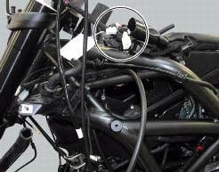
Location of left hand handlebar switchgear set connection.
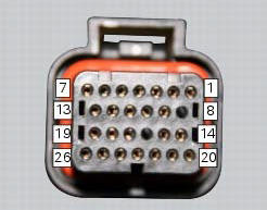
Pin numbering for wiring harness side dashboard connector.
Checks
Test turn indicator reset button function. When the button is pressed, there must be continuity between its two electric terminals (pin 3 and pin 1).
Check that there is a voltage of 5v on pin 1 of the turn indicator reset button arriving from dashboard pin 17.
Check the integrity of the electrical circuit and connections (short-circuits to ground, short-circuits to vdc, open circuits).
If none of the aforementioned tests identifies the problem, replace the dashboard.
Note
Check integrity of electric circuit - short-circuit to vdc = with dashboard on, using a voltmeter, a voltage is measured between the wire tested and ground.
Check integrity of electric circuit - short-circuit to ground = with the battery cables disconnected, using an ohmmeter, continuity is detected between the wire tested and ground.
Check integrity of electric circuit - open circuit = with the battery cables disconnected, using an ohmmeter, no continuity is detected between the two ends of the wire tested.
 Dashboard menu option scrolling not possible
Fault codes
Dds: no fault code displayed
Dashboard: no fault code displayed
Location of connections and components
Location of left hand handlebar switchgear set connection.
Pin numbering ...
 Gear indicator display on dashboard shows dashes, engaged gear not displayed
correctly, idle speed irregular
with gearbox in neutral
Gear indicator display on dashboard shows dashes, engaged gear not displayed
correctly, idle speed irregular
with gearbox in neutral
Fault codes
Dds: gear sensor diagnosis -> short circuit to ground or open circuit (s.C.
Gnd or c.O.) - Short circuit to vdc (s.C. Vdc)
- congruence (generic error - signal not correct).
Dash ...
Other materials:
Removal of the camshafts
Unscrew and remove the screws (7) and the o-rings (8) from the cylinder head
covers.
Remove the cylinder head cover (6).
Remove the gaskets (4) and (9).
Repeat the same procedure for the other cylinder head cover. Unscrew the
screws (3) securing the camshaft supports.
Withdra ...
Refitting the cylinder heads pulleys/fixed tensioners
Check that the keyway on the end of the camshaft is in good condition and
without burrs.
Fit a woodruff key (b) in the keyway of each camshaft.
Fit the pulley (11) on the camshaft, inserting the woodruff key in the in the
slot (c) in the pulley.
Apply the recommended grease to the t ...
Removal of the engine
In order to remove engine you must first remove a series of other components
from the motorcycle.
Most of these removal procedures are described in the relative sections of this
manual.
The following flow chart illustrates the logical sequence in which the parts are
to be removed from th ...