
Ducati Diavel Service Manual: Ignition coils
Introduction
The engine control system of the diavel includes two ignition coils: one for the horizontal cylinder and one for the vertical cylinder. These coils are installed directly in the spark plug wells. A diode is installed on the secondary winding inside the coil, which prevents the unintentional generation of a spark at the spark plug as a result of variations in voltage induced on the secondary winding itself when the primary winding charge phase starts. During this phase, the diode is inversely polarised and does not allow current to pass. Conversely, during the phase in which the ecu annuls the current circulating in the primary winding, the diode is directly polarised and allows spark generation on the spark plug.
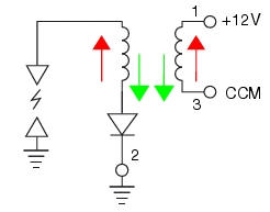
The image shows the internal electric configuration of the coil. During the primary coil phase, the polarities of the two voltages inversely polarise the diode (red arrows). When the ecu interrupts power to the primary circuit, the diode is polarised directly (green arrows), allowing spark generation on the spark plug. Pins 1, 2 and 3 are located on the primary connection of the coil.
The diagram illustrates the qualitative variation over time of the charge current for the primary coil winding. The ecu determines the instant t1 (in relation to this time and engine speed, the ignition advance value in degrees is calculated), in which the connection to ground on pin3 is interrupted, triggering the spark on the spark plug. At t0, the ecu grounds coil pin 3, and current begins to circulate in the primary winding. The instant t0 is calculated by the ecu to allow the necessary time interval (t1 - t0) to charge the primary coil winding correctly. Typically, the interval t1 - t0 increases with increasing engine speed.
Component assembling position
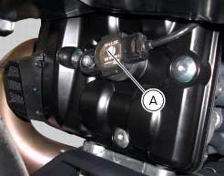
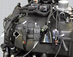
Installation location of horizontal cylinder coil (a).
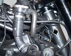
Location of horizontal cylinder coil connection.
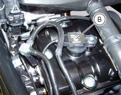
Installation location of vertical cylinder coil (b).
Location of vertical cylinder coil connection.
Connection wiring diagram
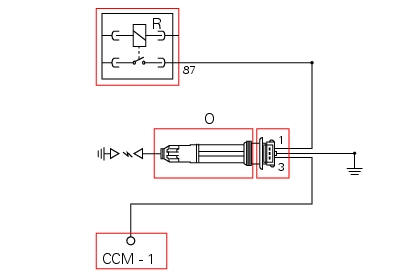
O horizontal cylinder coil, r injection relay. Ccm engine control connection, 1 power connection (12v) via injection relay (brown/white - bn/w), 3 connection to control unit (grey/black - gr/bk), 2 ground (black/bk).

V vertical cylinder coil, r injection relay. Ccm engine control connection, 1 power connection (12v) via injection relay (brown/white - bn/w), 3 connection to control unit (grey/yellow - gr/y), 2 ground (black - bk).
In the event of fault
The cylinder associated with the faulty coil does not function. The injector associated with the faulty coil is disabled.
Fault codes generated and possible correlated faults fault codes generated by engine control unit and displayed by dds (vertical ignition diagnosis (coil 2), horizontal ignition diagnosis (coil 1)):
- Coil 1 (cylinder 1 - horizontal) and/or coil 2 (cylinder 2 - vertical), open circuit: check integrity of electric circuit and electrical connections.
- Coil 1 (cylinder 1 - horizontal) and/or coil 2 (cylinder 2 - vertical), short circuit to vdc: check integrity of electric circuit and electrical connections.
- Coil 1 (cylinder 1 - horizontal) and/or coil 2 (cylinder 2 - vertical), short circuit to ground: check integrity of electric circuit and electrical connections.
Note
Check integrity of electric circuit - short-circuit to vdc = with dashboard on, using a voltmeter, a voltage is measured between the wire tested and ground.
Check integrity of electric circuit - short-circuit to ground = with the battery cables disconnected, using an ohmmeter, continuity is detected between the wire tested and ground.
Check integrity of electric circuit - open circuit = with the battery cables disconnected, using an ohmmeter, no continuity is detected between the two ends of the wire tested.
The dashboard service display shows the error "coil" and the eobd warning light activates.
Possible correlated faults:
- If the engine does not start and the primary coil windings are not receiving 12v power, check injection relay function (see paragraph "injection relay") of this section.
- If the engine runs on one cylinder only and there is no spark at one of the two spark plugs, try swapping the coils. If the fault (no spark) follows the coil, the coil itself is faulty. If the fault does not follow the coil, the relative control circuit is faulty.
- If the engine runs unevenly (backfires and torque delivery is uneven), check that pin 2 on the primary coil winding is grounded correctly. If necessary, replace the coils as the respective internal diode may be damaged (short circuited).
The coils may be activated from the dds to check for sparking across the spark plug electrodes (during the test, the spark plug threads must be correctly grounded) if none of the aforementioned tests identify the problem and the coils are in proper working order, replace the engine control unit.
Component replacement methods
The coils replacement do not foresee particular measures, proceed as described in sect. 4-3, Spark plugs replacement.
 Anti-pollution system and auto-adaptive strategy
Efficacy of the catalytic converter and oxygen sensors
To comply with current emissions legislation, the diavel is equipped with a
trivalent catalytic converter, which oxidises co
(carbon monoxide ...
 Injectors
Introduction
The injectors used on the diavel are top feed units, meaning that fuel is fed
into the top of the injector itself. The
injectors contain a winding which raises a needle when electrica ...
Other materials:
Low hands free key (hf) battery level
The activation of this (amber yellow) "warning" indicates that the hands free
system has detected that the battery that
permits the active key (a) to communicate and turn the vehicle on is almost
discharged.
Note
In this case replace as soon as possible the battery as indicated in sect.
6 - ...
Identification data
All ducati motorcycles have two identification numbers, for
frame (fig. 1) And engine (fig. 2).
Note
These numbers indicate the motorcycle model and
should be quoted when ordering spare parts.
...
Reassembly of the timing pulleys
Fit the pulley (11) on the flange (24), aligning the timing mark (d) on the
pulley with the timing mark on the (e) on the
flange.
Install the washer (23) up against the pulley, aligning the timing notch (f)
with the timing marks on the pulley and the
flange.
Insert the three screws (22) ...