
Ducati Diavel Service Manual: Refitting the gear interlock plunger and pawl assembly
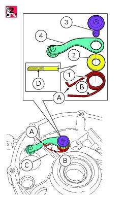
On the special screw (3), fit the gear pawl lever (4), orienting it as shown in the figure, the washer (2) with the square edge side (d) facing the clutch-side crankcase half, and the spring (1), positioning it so that the hook end (a) is facing the gear pawl lever. Locate the hook end (a) of the spring on the gear pawl lever as shown in the figure.
Apply threadlocker to the screw thread. Start the screw in the crankcase half. Position end (b) of the spring so that it rests against rib (c) of the crankcase half, as shown in the figure. Tighten the screw (3) to a torque of 18 nm (min. 16 Nm - max. 20 Nm) (sect. 3 - 3, Engine torque settings). Manually move the gear stopper to check for proper spring operation.
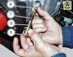
Grease and then fit the ball (8), spring (7), and seal (6) to the gear interlock plunger (5).
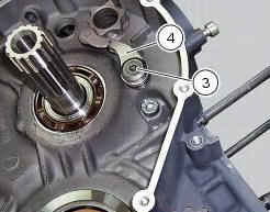
Lock the plunger (5) to a torque of 30 nm (min. 27 Nm - max. 33 Nm) (sect. 3 - 3, Engine torque settings).
 Disassembly of gear interlock plunger and pawl assembly
Unscrew the interlock plunger screw (5) and remove the seal (6), spring (7)
and the detent ball (8).
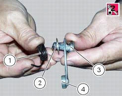
Unscrew the clutch-side crankcase half screw (3) and remove the pawl (4),
washer (2) a ...
 Refitting the gear selector lever
Position the gearbox drum selector fork in the centre of the gear rollers.
Position the gear selector lever (21) together with control shaft, spring and
plate into the chain-side crankcase half.
...
Other materials:
Default function (resetting ducati default parameters)
This function resets the parameters set by ducati for each riding style.
To access the function it is necessary to view the ""setting" menu", using
buttons (1) "s" or (2) "t" select the "riding
mode" function and press the reset button (3) to enter the following page.
Use button (1) "s" or ...
Disassembly of the clutch cover
Remove the plug (14) and its o-ring (13), the plug (17) and its o-ring (15)
from the cover.
Undo the fixing screw (16) of the inner cover (19).
Remove the inner cover (6) and soundproofing panel (18).
Remove the circlip (10) and withdraw the shim (9) and the sealing ring (8).
The dri ...
Removing of the rear footrests
The removal of the rear footrests is described for the right side but it is
the same for both.
Undo the pin (13) and remove the rh rear footrest (12) from the frame.
Recover washer (8) and the o-rings (9).
If necessary remove the rubber footrest (11) of the footrest (12).
...