
Ducati Diavel Service Manual: Number plate light not working
Fault codes
Dds: no fault code displayed.
Dashboard: no fault code displayed.
Location of connections and components
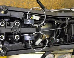
Location of rear turn indicator and number plate light connection.
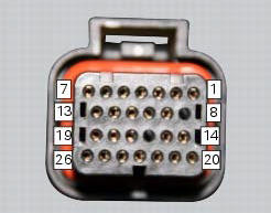
pin numbering for wiring harness side dashboard connector.
Checks
The number plate light receives pwm power supply from the dashboard. If necessary, power the number plate light with a 12 v external power supply to test function (connect correctly as indicated in the wiring diagram).
Check congruence of the ground connection on the number plate light.
Check the integrity of the electrical circuit and connections (short-circuits to ground, short-circuits to vdc, open circuits).
If none of the aforementioned tests identifies the problem, replace the dashboard.
Note
Check integrity of electric circuit - short-circuit to vdc = with dashboard on, using a voltmeter, a voltage is measured between the wire tested and ground.
Check integrity of electric circuit - short-circuit to ground = with the battery cables disconnected, using an ohmmeter, continuity is detected between the wire tested and ground.
Check integrity of electric circuit - open circuit = with the battery cables disconnected, using an ohmmeter, no continuity is detected between the two ends of the wire tested.
 High beam flash not working - start/stop lap function not working
Fault codes
Dds: no fault code displayed.
Dashboard: no fault code displayed.
Wiring diagram
Db dashboard connection, s high beam flash button. 7 Orange - o, 1
red/blue - r/b.
Location of ...
 Running lights not working
Fault codes
Dds: no fault code displayed.
Dashboard: no fault code displayed.
Location of connections and components
(A) low / high beam and parking light connections
rear running light and ...
Other materials:
Checking the engine timing
Set the engine to the configuration described for the "checking and adjusting
the valve clearances", previously indicated.
Install tool 88765.1188 (G) in the spark plug bore to determine the piston tdc,
the gauges (h) on the tool 88765.1518
And the timing check tool (degree wheel (l) 887 ...
Reassembly of the clutch-side crankcase cover
Fit the plug (14) and the gasket (13). Fit the plug (17) and the gasket (15).
If the bush has been replaced, fully seat the new bush (7) in the slot in the
cover using a suitable drift and a press.
If the sealing ring (8) needs to be renewed, fit the new seal into the crankcase
cover, po ...
Steering head: steering
Screw
Steering head
Screw
Lower rh u-bolt
Lower lh u-bolt
Bearing
Screw
Sealing ring
Washer
Spacer
Washer
Nut
Washer
Screw
Bottom yoke
Dowel
Nut
Screw
Special screw
Clip nut
Left-hand support
Front splashguard
Right-hand support
Front support
S ...