
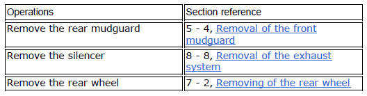
Ducati Diavel Service Manual: Replacing the rear phonic wheel sensor
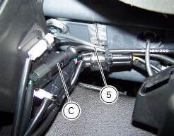
Disconnect the rear abs sensor (5) connector (c) from the main electric wiring.
Open all the retainer clamps of the rear abs sensor cable (5): refer to table of sect. 7 - 6, Flexible wiring/hoses positioning.
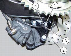
Remove the rear abs sensor (5) from its seat on the rear calliper mounting bracket (e), undoing the retaining screw (1) and collect the calibrated gasket (3).
Before refitting, make sure that the contact parts between the rear abs sensor (5) and its seat are not damaged and are perfectly clean.
Fit the new rear abs sensor (5) on its seat inserting the screw (1).
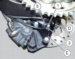
Check the air gap between the new rear abs sensor (5) and the rear phonic wheel (d) as indicated in sect. 7 - 7, Adjusting of the air-gap phonic wheel sensor.
Fix the sensor to the calliper holder bracket tightening the screw (1) to a torque of 10 nm +/- 10% (sect. 3 - 3, Frame torque settings).
Connect the connector (c) to the main wiring.
Restore all the retainer clamps of the rear abs sensor cable (5): refer to table of sect. 7 - 6, Flexible wiring/hoses positioning.


 Replacing the front phonic wheel sensor
Disconnect the front abs sensor (2) connector (a) from the main electric
wiring.
Open all the retainer clamps of the front abs sensor cable (2): refer to table
of sect. 7 - 6, Flexible wiri ...
 Removing of the abs control unit
Drain the hydraulic fluid that is inside the front and rear braking system
tubes by disconnecting them from the master
cylinder and the calliper (sect. 4 -3, Changing the brake fluid).
Disco ...
Other materials:
Removal of the evaporative emissions canister
Loosen the screws (9) securing the plate (8) to the tank.
Slightly pull the plate (8) with the canister (13), remove the clamps (3) and
(12) and connect hoses (7) and (14).
Release the retainers (b) of the plate (8) to remove it from the canister
(13).
Disconnect the hose ...
Checking valve lift
Set the engine to the configuration described for the "checking and adjusting
the valve clearances", previously indicated.
Position the tool 88765.1518 On the cylinder head: the part marked "a" should be
on the intake side and the part
marked "s" should be on the exhaust side.
Seat the pl ...
Location of elements on motorcycle
(A) injection relay; (b) etv relay (throttle valve operating engine); (c)
radiator fan relay; (d) hands free relay.
(E) ecu; (g) bbs (black box system or central electronics); (f) abs hydraulic
unit with integrated control unit.
Fuses located at the rear left of the vehicle.
...