
Ducati Diavel Service Manual: On/off switch on handlebar
Introduction
The on/off switch on the handlebar is used to switch the dashboard on and off, if a key has been detected, and start the engine.
With the switch turned to "run off" (centre position), pushing downwards switches the dashboard on or off (activating the button inside the switch).
Wiring diagram

The button inside the on/off switch receives 12 volt power directly from the battery via the main 30 a fuse. When pressed, it sends the 12 volt power to the hands free system, which detects activation of the button. On/off switch pin 8, light blue wire (lb), on/off switch pin 5, red wire (r).
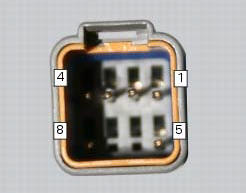
Pinout of right hand handlebar switch connection, wiring harness side.
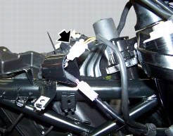
Location of the right hand handlebar switch connection.
Error codes
The hands free system generates no fault code in the event of a fault of the on/off switch on the handlebar.
Electrical characteristics and checking component
The switch receives 12 volt power directly from the battery via the main 30 a fuse.
Check for 12 volts on pin 5 of the switch.
Check for 12 volts on pin 6 of the hand free system side connector with the switched pressed. The voltage measured must be 0 volts when the switch is not pressed.
In the event of fault
In the event of a fault of the on/off switch on the handlebar, the button integrated into the hands free system may be used instead.
Installation location
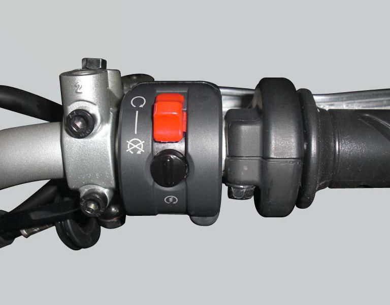
The image shows the location of the on/off switch, near the throttle grip on the right hand side of the handlebar.
 Communication antenna
Introduction
The communication antenna enables the hands free system to detect and
communicate with the active or passive key.
The active key is detectable within a range of 1.5 Metres, whereas ...
 The hands free relay
Introduction
This relay provides key on +15 power to all the devices on the motorcycle.
Functionally, it replaces the conventional
ignition switch.
Wiring diagram
The hands free relay receiv ...
Other materials:
Recharging the battery
Examine the label on the battery showing the check intervals in order to
determine when to test the voltage.
Charge the battery if the open circuit voltage is lower than 12.8 V. Leaving
the battery discharged for more than one
month could damage it. Check the battery charge with a voltmete ...
Removal of the lubrication system
Disconnect the sensor (12) of the main wiring.
Open the pipe grommet (11).
Undo the screw (8) and slide out the plate (9).
Slide the tubes (7) out of the half-casing having care not to damage the tubes
o-rings (a) that guarantee the coupling
sealing.
Undo and remove the sc ...
Removal of the gearbox assembly
Withdraw the selector fork shafts (30).
Move the forks (28) and (29) to disengage them from the slots in the selector
drum (14).
Withdraw the selector drum (16) taking care not to lose shims (31) and (27)
mounted on the shaft. Note that the
positions of the shims must not be inverte ...