
Ducati Diavel Service Manual: The hands free relay
Introduction
This relay provides key on +15 power to all the devices on the motorcycle. Functionally, it replaces the conventional ignition switch.
Wiring diagram
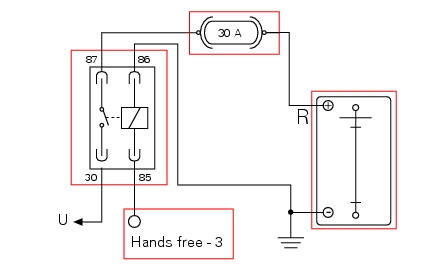
The hands free relay receives +12 volt power directly from the battery via the main 30 a fuse. Hands free - 3: pin 3 on hands free system connection. "U": current consumers requiring +12 volt in key on state (key on +15). Pin 30 red/white wire (r/w), pin 86 black wire (bk), pin 87 red wire (r), pin 85 red/yellow wire (r/y)
Error codes
The hands free system generates no fault code in the event of a hands free relay fault.
Electrical characteristics and checking component
The relay contact must close (continuity between pin 87 and pin 30) when the internal electric winding is powered with 12 volts (pin 86 and pin 85).
In the event of fault
In the event of a hands free relay fault, the engine stops (if running) or will not start. The relay is not commanded by the hands free system.
Installation location
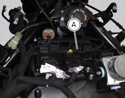
This image shows the location of the hands free relay (a). It is located on the relay supporting bracket.
Component replacement methods
No special measures are necessary in order to replace the hands free relay.
 On/off switch on handlebar
Introduction
The on/off switch on the handlebar is used to switch the dashboard on and
off, if a key has been detected, and start the
engine.
With the switch turned to "run off" (centre positio ...
 Active key
Introduction
The active key (1) communicates with the hands free system by radio. In order
to function, the key must be within a 1.5
Metre radius from the antenna (located in the document compartm ...
Other materials:
Dashboard diagnosis
This function identifies any abnormal vehicle behaviours.
The dashboard activates any abnormal vehicle behaviours in real time (errors).
At key-on (at the end of the check) one or more "errors" are displayed in red
(only if they are active).
When an "error" is triggered, the indication (r ...
Using a multimeter to check the electrical systems
Introduction
This instrument allows you to measure resistance, voltages, and current
values. Multimeters can be divided into two basic
types: analogue and digital display multimeter. An analogue multimeter has a
pointer display. The dial is marked with the
scales to be used for measurement of ...
Key-on/key-off using the key on the hands free lock with the passive key
Key-on can be performed by pressing the button (7) on the
hands free lock and with the presence of the passive key (4,
fig. 77).
Note
The passive key (4, fig. 77) Has a range of a few cm,
therefore the key (4, fig. 77) Must be positioned near the
antenna (2). Remove the seat (see "remova ...