
Ducati Diavel Service Manual: Reassembling the electrical components support
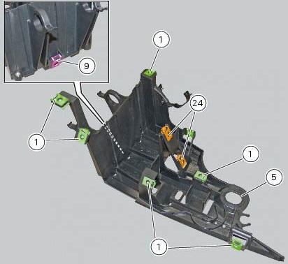
Check the presence of clips (1), (9) and (24) on the support (5).
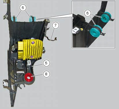
Check the presence of rubber pads (6) and (8) and of cable grommet (7).
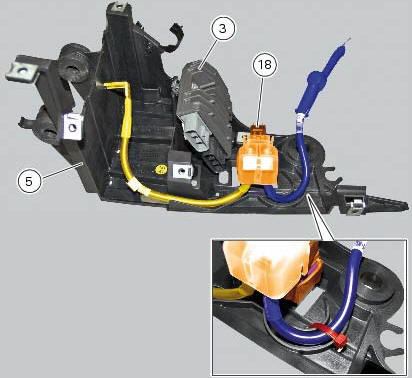
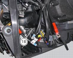
Check that the voltage regulator (3) and the solenoid starter (18) are in place on the support (5) with their wiring as shown.
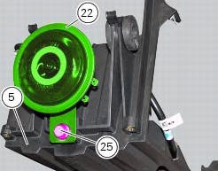
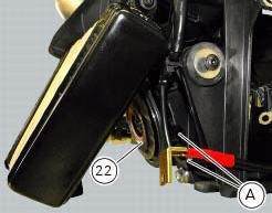
The horn (22) must be fixed to the support (5) tightening the screw (25) to 18 nm +/- 10% (sect. 3 - 3, Frame torque settings).
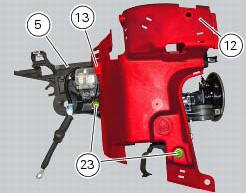
Check the presence of the grommet (13) on the cover (12).
Fit cover (12) on the support (5) by tightening the screw (23) to a torque of 4 nm +/- 10% (sect. 3 - 3, Frame torque settings).
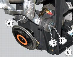
Fit the electrical components support (5) on the vehicle by engaging it in the retaining pin (b) on the cooler supporting bracket.
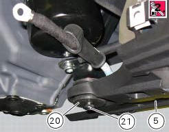
Apply the recommended threadlocker to the screw (21).
Start the screw (11) with washer (10) and the screw (21) with spacer (20).
Tighten the screw (11) to a torque of 10 nm +/-10% (sect. 3 - 3, Frame torque settings) and the screw (26) to a torque of 24 nm +/-10% (sect. 3 - 3, Frame torque settings).
Connect the connector (a) of horn (22) to the main wiring.
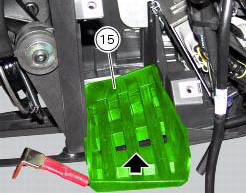
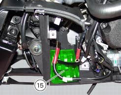
The mat (15) must be positioned as shown.
Reassemble the following elements located inside the electrical components support:
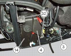
- The battery (14) as specified under section 6 - 2,battery;
- The voltage regulator (3) as specified under section 6 - 2,rectifier-regulator;
- The solenoid starter (18) as specified under section 6 - 3,solenoid starter;
After installing the battery, position the battery retaining bracket (4) by tightening the screws (32) to a torque of 5 nm +/- 10% (sect. 3 - 3, Frame torque settings).
Check wiring position as described in chapter: "routing of wiring on frame", sect. 6 -1.
 Removing the electrical components support
Remove the following elements located inside the electrical components
support:
The battery fixing bracket (4) and the battery (14) as specified under
section 6 - 2, battery;
The voltag ...

Other materials:
Gearbox shafts
Shim, thickness 1
Gearbox primary shaft
Shim, thickness 0.5
Needle roller bearing
5Th speed driving gear
Splined washer, thickness 0.5
Circlip
3Rd- 4th speed driving gear
6Th speed driving gear
2Nd speed driving gear
Shim, thickness 1.8
Splined washer, thickness 0.5
Sp ...
Warranty
In your own interest, and in order to guarantee product
reliability, you are strongly advised to refer to a ducati dealer
or authorised service centre for servicing that requires any
particular technical expertise.
Our highly skilled staff have the tools required to perform any
servicing job ...
Refitting the seat
Note
Apply recommended grease to the hole (a) of latch (6).
Fit the seat (1) as follows: insert the tabs (b) (on the front side) under
the rubber pads (c) of the gloves compartment;
then push the seat rear side until hearing the lock latch click.
...