
Ducati Diavel Service Manual: Removing the electrical components support
Remove the following elements located inside the electrical components support:
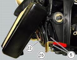
- The battery fixing bracket (4) and the battery (14) as specified under section 6 - 2, battery;
- The voltage regulator (3) as specified under section 6 - 2,rectifier-regulator;
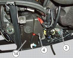
- The solenoid starter (18) as specified under section 6 - 3,solenoid starter;
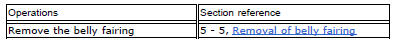
Remove the connector (a) of horn (22) from the main wiring.
Undo the screw (25) and remove the horn (22) from the vehicle.
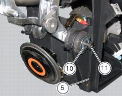
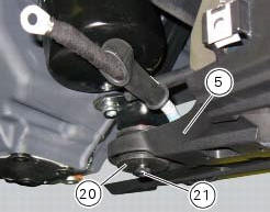
Loosen screws (11) and (21) and recover the washer (10) and the spacer (20).
Remove the electrical components support (5).
Pay attention to the main wiring branch and to any other wiring inside of it.
Refer to the tables reported in this section for the components position.
 Electrical components support
Clip
Screw
Voltage regulator
Battery fixing bracket
Battery support
Vibration damper mount
Hose clip
Vibration damper mount
Clip
Washer
Screw
Cover
Cable grommet
Batte ...
 Reassembling the electrical components support
Check the presence of clips (1), (9) and (24) on the support (5).
Check the presence of rubber pads (6) and (8) and of cable grommet (7).
Check that the voltage regulator (3) and the solenoi ...
Other materials:
Tips on how to select the sensitivity level
Warning
The 8 level settings of the dtc were calibrated using tyres of the
same make, model and size as those originally fitted to
the motorcycle.
The use of tyres of different size to the original tyres may alter the operating
characteristics of the system.
In the case of minor differen ...
Riding mode set indication
This function indicates the "riding style" set for the vehicle.
Three "riding modes" are available: sport, touring and
urban.
Each riding mode can be changed using the "riding
mode" function.
Note
The background of the riding mode (sport, touring
or urban) i ...
Removal of the cooling system hoses and unions
Loosen the clips (21) that secure the radiator/thermostat sleeve (40) and the
radiator/plug sleeve (24) to the water
radiators.
Loosen clips (25) and (43) that secure the breather pipe (26) to the
radiator/plug sleeve (24) and to the left radiator.
Loosen the clips (34) securi ...