
Ducati Diavel Service Manual: Electrical components support
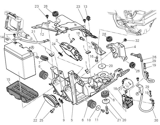
- Clip
- Screw
- Voltage regulator
- Battery fixing bracket
- Battery support
- Vibration damper mount
- Hose clip
- Vibration damper mount
- Clip
- Washer
- Screw
- Cover
- Cable grommet
- Battery
- Battery mat
- Screw
- Bracket
- Solenoid starter
- Spring washer
- Spacer
- Screw
- Horn
- Screw
- Clip
- Screw
- Rubber pad
- 30 A fuse
- Solenoid starter cable - starter motor
- Screw
- Screw
- Battery ground cable - engine
- Special screw
Spare parts catalogue
Diavel abs battery support
Diavel carbon abs battery support
Important
Bold reference numbers in this section identify parts not shown in the figures alongside the text, but which can be found in the exploded view diagram.
 Reassembly of belly fairing
Position the oil cooler shield (7) inserting the tab (a) into the slit (b) in
the electrical components support (s).
Note
On refitting, make sure that the tab (c) remains positioned under the
re ...
 Removing the electrical components support
Remove the following elements located inside the electrical components
support:
The battery fixing bracket (4) and the battery (14) as specified under
section 6 - 2, battery;
The voltag ...
Other materials:
Checking and overhauling the components
Clearance between the clutch drum and friction plates
Insert a friction plate (e) in the clutch drum (f) and measure the clearance
(s) with a feeler gauge.
Clearance "s" must not exceed 0.6 Mm.
If it does, renew the plates and, if necessary, the clutch drum.
Overhaul of the clutch plat ...
Setting menu
This menu is used to enable/disable and set some motorcycle functions.
To access the "setting menu" press and hold button (2) "t" for 3 seconds.
Note
When within this menu no other function can be displayed.
Important
For safety reasons, the setting menu can only be accessed when motorcycle
...
Removal of the movable tensioner/timing belt
Loosen the nut (8) and remove the washer (7) and the tensioner pulley (9)
from the pin (12) on the cylinder head.
Remove the timing belt (14) from the horizontal cylinder assembly.
Important
If the belts are to be re-used, mark the direction of rotation with an
arrow and also mark the cylin ...