
Ducati Diavel Service Manual: Recovery procedure in the event of hands free system fault
If the hands free system can no longer communicate with the other control
units over the can network (with the
dashboard or engine on), the following icon is shown on the tank dashboard:
The following image shows the icon appearing on the tank dashboard: this
indicates that the hands free system is not
connected to the can network or that it cannot communicate over the can network
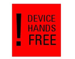
in the event of a hands free system fault, the following icon is displayed on
the tank dashboard: 
The following image shows the icon appearing on the tank dashboard: this indicates a hands free system fault if the engine was off before the fault occurred, starting the engine may not be possible.
If the engine was running before the fault occurred, the hands free system will not switch the engine off. Once the engine is switched off, however, starting the engine may no longer be possible.
 Recovery procedure in the event of electric steering lock fault
If any fault occurs during activation of the electric steering lock: for
example, if the pin jams, if the handlebar is moved
while the pin is deployed or if there is excessive strain on the electri ...
 Start procedure with pin code (no keys)
The motorcycle may be started without keys with a special procedure using the
dashboard and the switches on the
handlebar.
Note
This procedure is only possible if the pin code has been enabled
...
Other materials:
Tester power supply
The dds (1) part number 97900.0215 Can be powered from the vehicle as
follows:
From the mains power supply: by connecting the power supply connector
(n) to the network power supply (2) part no.
97900.0224;
From the motorcycle: connecting the corresponding cables (see paragraph
...
Resetting turn indicators not possible - accessing dashboard menu not
possible
Fault codes
Dds: no fault code displayed
Dashboard: no fault code displayed
Location of connections and components
Location of left hand handlebar switchgear set connection.
Pin numbering for wiring harness side dashboard connector.
Checks
Test turn indicator reset button function. Wh ...
Stored lap display function
This function displays the stored laps.
To access the function it is necessary to view the "setting" menu page 48, using
button (1, fig. 14) ?"" or (2, fig.
14) ?" " select the "lap" function and
press the reset button
(12, fig. 12) To go to next pag ...