
Ducati Diavel Service Manual: Replacing the tank flange and fuel sensor
Loosen the screws (19) securing the fuel tank flange (20).
Remove the flange (20) from the tank (20).
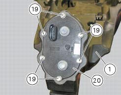
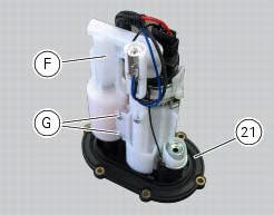
Recover the seal (21).
Undo and remove the two fixing screws (g) and move the protection (f).
Before reassembly, carefully remove any deposits or scale from all parts.
Note
The flange is supplied as a spare part complete with the fuel pump and pressure regulator: the entire flange assembly must be replaced in the event of malfunction.
 Refitting the filler cap
Position seal (18) in tank cap (10) as shown and reassemble following the
removal procedure in the reverse sequence.
In particular tighten the screws (17) to a torque of 3 nm +/- 10% (sect. 3 - ...
 Refitting the fuel tank flange
Insert the flange (20) in its housing in the fuel tank.
Apply prescribed threadlocker to the screws (9) and tighten to a torque of 6 nm
+/- 10% (sect. 3 - 3, Frame torque
settings), following th ...
Other materials:
Reassembling the electrical components support
Check the presence of clips (1), (9) and (24) on the support (5).
Check the presence of rubber pads (6) and (8) and of cable grommet (7).
Check that the voltage regulator (3) and the solenoid starter (18) are in
place on the support (5) with their wiring as
shown.
The horn (22) mus ...
Timing system
Central external cover
Air filter
Horizontal cylinder timing belt cover
Screw
Filter support
Screw
Washer
Nut
Tensioner pulley assembly
Circlip
Camshaft pulley
Tensioner pin
Idler pulley assembly
Timing belt
Nut
Key
Spacer
Camshaft pulley
Driveshaft pulley ...
Specific tools for the frame
88713.1072 Drift to install half bearing in bottom yoke
88713.2562 Chain assembly tool
88713.1058 Wrench for steering shaft nut
88713.1062 Tool for installing steering head bearings
88713.2951 Rear wheel balancing tool
88713.3211 Wrench for adjustment of the eccentric hu ...