
Ducati Diavel Service Manual: Removal of belly fairing
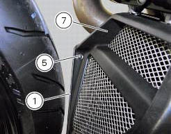
Loosen and remove the screws (5) and (8) that secure the oil cooler (7) to the rh (1) and lh (2) belly fairings.
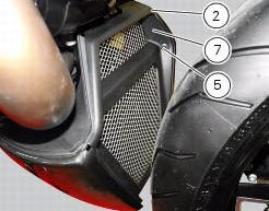
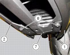
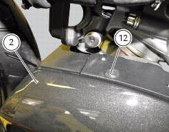
Remove the lh belly fairing (2) by loosening the screws (3) with relevant washers (4) and the screws (12).
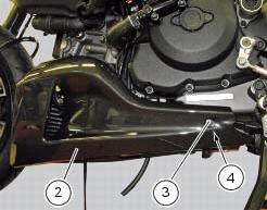
Follow the same procedure to remove the rh belly fairing (1).
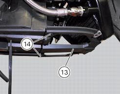
Loosen the screws (14) and remove the bracket (13 from the electrical components support.
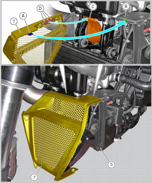
Remove the oil cooler shield (7) from the electrical components support (s) by releasing the tab (a) from the slit (b) and tab (c) from retainers (d).
 Belly fairing
Rh belly fairing
Lh belly fairing
Special screw
Nylon washer
Screw
Central belly fairing
Oil cooler shield
Special screw
Clip
Washer
Clip
Screw
Bracket
Screw
Spare ...
 Reassembly of belly fairing
Position the oil cooler shield (7) inserting the tab (a) into the slit (b) in
the electrical components support (s).
Note
On refitting, make sure that the tab (c) remains positioned under the
re ...
Other materials:
Transmission
Wet clutch controlled by the lever on left-hand side of the
handlebar.
Transmission from engine to gearbox primary shaft via spur
gears.
Front chain sprocket/clutch gearwheel ratio:
33/61
6-speed gearbox with constant mesh gears, gear change
pedal on left side of motorcycle.
Gearbox ou ...
Belly fairing
Rh belly fairing
Lh belly fairing
Special screw
Nylon washer
Screw
Central belly fairing
Oil cooler shield
Special screw
Clip
Washer
Clip
Screw
Bracket
Screw
Spare parts catalogue
Diavel abs belly fairing
Diavel carbon
abs
belly fairing
Important
Bold refere ...
Removing the silencer
Loosen the clamp (38) that retains the silencer (4) to the complete exhaust
system.
While holding the nut (8), loosen the screw (1) and remove the silencer (4)
from the motorcycle.
Loosen the screws (40) and remove the silencer guard (41).
...