
Ducati Diavel Service Manual: Disassembly of the rear brake control
The brake master cylinder is supplied only as a complete unit; internal components cannot be replaced.
To disassemble the master cylinder's outer parts, follow the indications given in the exploded view at the beginning of this section.
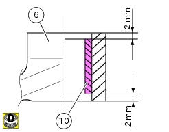
If the bush (10) inside the brake pedal (6) needs to be replaced, grease the external surface and fit the new bush using a press to insert it. The bush must be placed at 2 mm from the pedal external face.
To disassemble the various parts of the system, refer to the exploded view at the beginning of this chapter.
Warning
After performing an operation on the rear brake control, check the brake pedal position following the instructions detailed in sect. 4 - 3, Adjusting the position of the gear change and rear brake pedals.
 Removing of the rear brake control
Warning
The brake master cylinder manufacturer advises against servicing the
brake master cylinder due to the safety critical
nature of this component.
Incorrect overhaul can endanger the rider ...
 Refitting the rear brake control
If the pushrod (18), clip (30) and fork (31) assembly has been dismantled,
reassemble it by screwing the nut (29) onto
the rod (18) and then screw the rod into the fork (31) to obtain the measureme ...
Other materials:
Front and rear mudguard
Front mudguard
Washer
Rivet
Clip
Screw
Spacer
Screw
Rear mudguard
Screw
Spare parts catalogue
Diavel abs rear swingarm
Diavel abs belly fairing
Diavel carbon
abs
rear swingarm
Diavel carbon
abs
belly fairing
Important
Bold reference numbers in this section identif ...
Disassembly of rear shock absorber - rocker arm - linkage assembly
Undo the screw (15) and remove the rear shock absorber (11) from the rocker
arm (18).
Undo
Undo the screw (14) and the nut (21) and remove the linkages (10) and (12)
from the rocker arm (18).
The rocker arm movement is obtained by needle roller bearings (9) rotating on
a spacer (1 ...
Low battery level
The activation of this (amber yellow) "warning" indicates that the status of
the battery vehicle is low.
It is activated when the battery voltage is ¼ 11.0 Volt.
Note
In this case, ducati recommends charging the battery as soon as possible
with the specific device, as it is possible th ...