
Ducati Diavel Service Manual: Reassembly of belly fairing
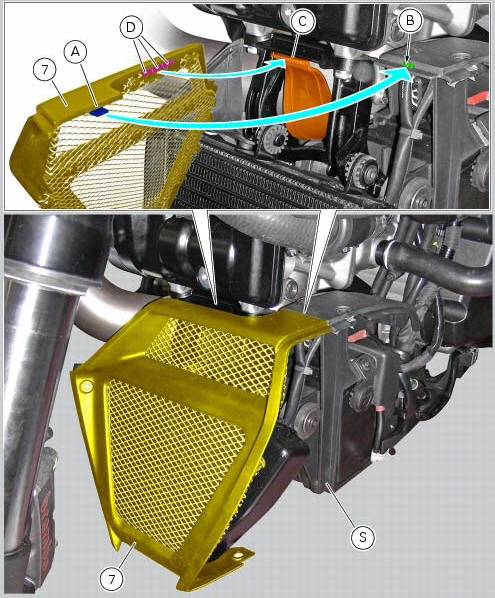
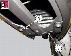
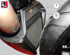
Position the oil cooler shield (7) inserting the tab (a) into the slit (b) in the electrical components support (s).
Note
On refitting, make sure that the tab (c) remains positioned under the retainers (d) of the shield (7).
Fit clips (11) on bracket (13) and orient them as shown in the figure.
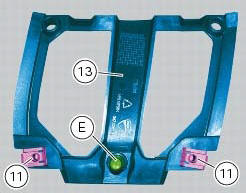
Apply rubber lubricant to the pin (e) of the bracket (13).
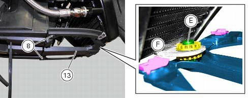
Insert pin (e) in the vibration damping pad (f) of the oil cooler.
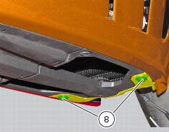
Fit the bracket (13) on the electrical components support, and tighten the screws (8) to a torque of 4 nm +/- 10 % (sect. 3 - 3, Frame torque settings).
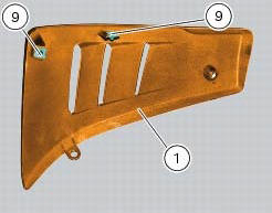
Fit clips (9) on lh belly fairing (2) and orient them as shown in the figure.
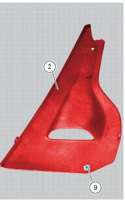
Put the lh belly fairing (2) in position by engaging slot (e) in the electrical components support, as shown in the figure.
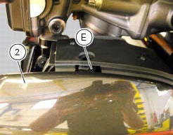
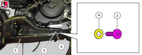
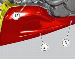
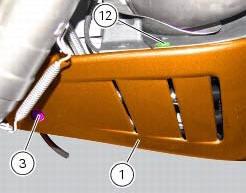
Apply recommended threadlocker on screws (3) and (12).
Fit the nylon washer (4) on the screw (3).
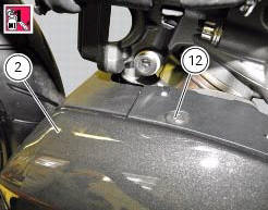
Fix the lh belly fairing (2) to the electrical components support by starting the screws (3) on the rear side, and the screw (12) on the upper side.
Apply recommended threadlocker to the screws (5) and (8).
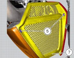
Fix the lh belly fairing (2) to the oil cooler shield (7) by starting the screw (8) on the lower side, and the screw (5) on the front side.
Fit the clips (9) on the rh belly fairing (1) orienting it as shown in the figure; follow the same procedure to refit the lh belly fairing (2).
Tighten to a torque of 4 nm +/- 10% (sect. 3 - 3, Frame torque settings) the screws (3), (5), (8) and (12) to fix the belly fairings (1) and (2) and the oil cooler shield (7).
 Removal of belly fairing
Loosen and remove the screws (5) and (8) that secure the oil cooler (7) to
the rh (1) and lh (2) belly fairings.
Remove the lh belly fairing (2) by loosening the screws (3) with relevan ...
 Electrical components support
Clip
Screw
Voltage regulator
Battery fixing bracket
Battery support
Vibration damper mount
Hose clip
Vibration damper mount
Clip
Washer
Screw
Cover
Cable grommet
Batte ...
Other materials:
Airbox - throttle body
Airbox
O-ring
Injector
Throttle body assembly
Screw
Clamp
Intake manifold
Screw
Pressure sensor
Screw
Clamp
Hose
Sealing washer
Intake manifold
Sealing washer
Screw
Screw
Spacer
Bracket
Rubber pad
Clamp
Hose
Clamp
Union
Washer
Hose
Cable gro ...
Removal of the front wheel
Support the bike so that the front wheel is raised from the ground.
Remove the front brake calliper (b) by unscrewing the two screws (a) securing
the calliper to the fork leg; do not
disconnect the calliper from the hose.
Warning
Do not operate the brake lever when the callipers are ...
Traction control (dtc) deactivated
The activation of this (amber yellow) "warning" indicates
that dtc (ducati traction control) has been turned off.
Note
In this case, ducati recommends being very careful
when riding as the vehicle behaviour will be different in
comparison to when operating with the traction control
...